IR Evaluation of Alaskan Oil Pipelines to Detect Trapped Water that Could Cause Corrosion Under Insulation (CUI)
InfraMation 2011 Application Paper Submission
Douglas Burleigh, La Jolla Cove Consulting, San Diego CA
Allen Sanders, Kakivik Asset Management, Anchorage AK
ABSTRACT
Infrared inspection is being used by KAM (Kakivik Asset Management) of Anchorage, Alaska to inspect oil pipelines on the North Slope of Alaska. The object of this inspection is to detect water trapped in the foam insulation around the steel pipes before it can cause corrosion that could result in a pipeline leak. This is referred to as Corrosion Under Insulation (CUI).
IR can scan multiple pipes quickly and is a good qualitative screening method. Anomalies found by IR are evaluated further using RT (“C-Arm” or other RT technique) or other NDT methods. RT is a relatively slow technique compared to IR, but it is capable of detecting both water and pipe wall thinning.
When the water level is high enough to reach the steel pipe, corrosion of the pipe can occur. In this case, the corrosion is from the outside of the pipe inward, while more “normal” corrosion is expected to take place from the inside out. Corrosion can eventually result in “rust through”, which will result in a leak.
Thermal modeling has been performed to predict the environmental conditions under which IR testing will be successful. IR test procedures have been written and a personnel certification program has been implemented.
INTRODUCTION
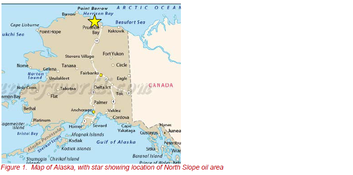
Safety is of paramount importance in the oil operations in the environmentally sensitive North Slope of Alaska. Substantial effort goes into the inspection and maintenance of pipelines to detect corrosion and to prevent oil leakage. KAM provides inspection and technical support at oilfield drill sites at the oilfields on the North Slope of Alaska, near the Arctic Ocean, well above the Arctic Circle.
The pipelines are part an oil production facility and they include gas lift (GL), gas injection (GI), production (PO), and water injection (WI) lines. The pipelines transport oil from the many individual drill sites to the site’s processing plant, where the oil is filtered to remove sand and water. The pipelines are not part of the main Trans Alaska Pipeline System (TAPS) that runs from the North Slope to Valdez AK.
For several years, KAM has been using IR as the primary inspection method for examining production pipelines at the drill sites and production facilities.IR can locate areas of water trapped in the foam insulation that covers steel piping systems. This trapped water can cause CUI (Corrosion Under Insulation).
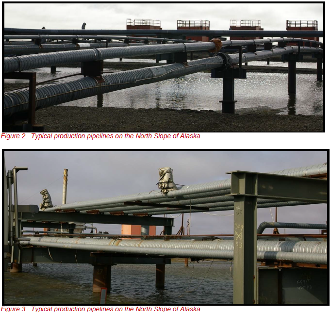
Typical production pipelines on the North Slope of Alaska carry oil or other fluids, whose temperature may vary from approximately 40° to 200°F (4° to 93°C). Oil comes out of the ground at elevated temperature, as it originates deep below the surface of the earth. This is beneficial, as viscosity is inversely proportional to temperature; warm oil flows much better than cold oil. If the oil gets cold enough, it will congeal, freeze, and stop flowing.
The (inner) pipe diameter varies from about 2 to 6 inches in diameter. The pipe wall thickness is constant, but varies from approximately 0.2 to 0.9 inch, depending on the diameter of the pipe. To reduce the cooling of the fluids in the cold climate, the steel pipe is insulated with high density “closed cell” foam. The thickness of the foam is constant along each pipe section, but varies from 2 to 6 inches depending on the size of the pipe inside.
To protect the foam insulation from weathering and impact damage, it is covered by a thin galvanized steel protective sheath that is approximately 0.04 inch thick. This sheath is referred to as a “wrap”, because it is formed from a sealed, spiral-wound strip of sheet metal.
Water from rain or snow sometimes gets through the outer wrap and into the foam insulation. Water may enter through any small opening, and is most commonly found around wrap seams, damaged wrap, and weld packs (pipe joints).
When water in the foam accumulates to a high enough level to come into contact with the steel pipe, corrosion can occur. The corrosion rate increases with increasing pipe temperature. Though it can take years, corrosion can eventually result in a hole in the pipe wall, causing the contents to leak out.
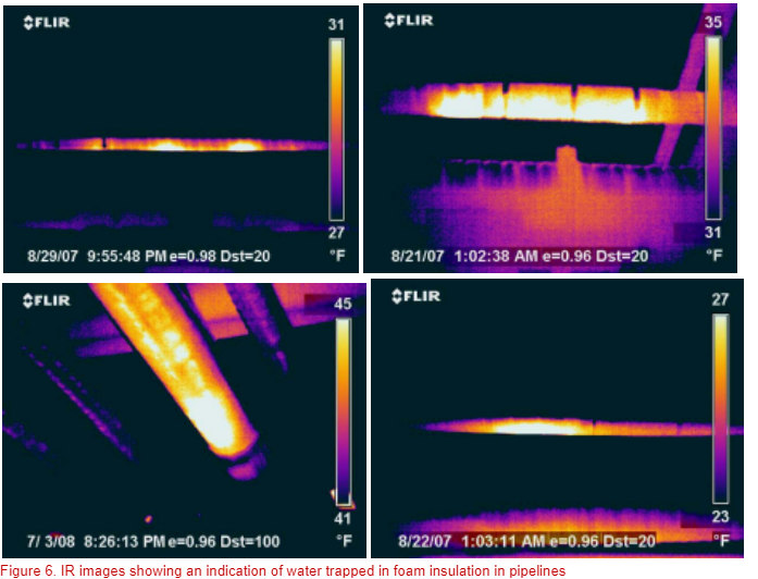
Figure 4 shows an idealized cross-sectional diagram of a pipe with water trapped in the foam insulation.
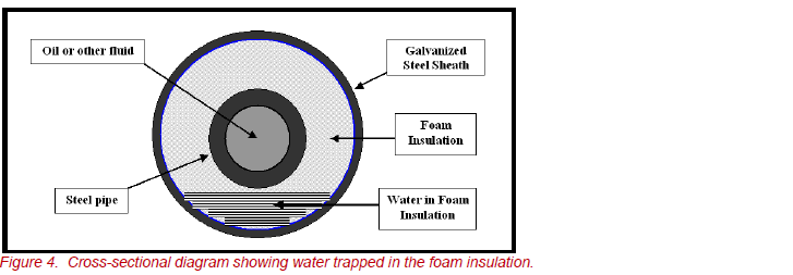
The distribution of the water in the foam insulation is not exactly as shown in Figure 4, tending to be more complex. Water migration through the foam will follow the path of least resistance, including large and small cracks in the foam. It will migrate due to capillary action and surface tension. Though the foam is described as “closed cell”, few foams actually have closed cells.
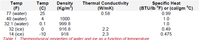
In Alaska, water trapped in the foam may freeze into ice if the temperature is low enough, regardless of the temperature of the inner pipe. The North Slope area can get as cold as –60°F in winter.
Ice has different thermophysical properties than water and the heat transfer (loss) will be increased. Table 1 shows some thermophysical properties of water and ice at various temperatures. Note that K of ice is approximately four times the K of water. And the specific heat of ice is half that of water. While the difference in K increases the heat loss when ice is present, it is not considered to be a significant problem.
However, when water freezes to ice inside the foam, it expands. This expansion may break the cells of the foam or create cracks in the foam. The numerous freeze and thaw cycles throughout the Alaskan year may structurally degrade the foam insulation at the location of the water, creating a path for water to migrate more easily towards the pipe.
IR inspection of these pipelines is generally performed with a FLIR P660 IR camera having an uncooled 640x480 detector array operating in the 7.5 to 13µm range. IR cameras with smaller arrays may be used but the lower resolution may result in a reduced probability of detecting trapped water.
IR indications are caused by a significant amount of water or a void in the foam insulation. Additional tests are performed to rule out IR reflections and conduction, which are false positives, and to determine whether a void (bubble) is present in the foam.
Voids are sometimes created in the foam during the manufacture of the insulated pipe system. Voids may occur at any point around the pipe, while water is generally found at the bottom. Voids in the foam do not require repair, but they may occasionally appear to be water, so the operator must determine whether an IR indication is water or a void. This is accomplished by tap testing and other observations.
IR images of indications of water are entered into a KAM computer database along with the location, the wind speed and ambient temperature measured by an anemometer, and a photo of the pipe. A computer model is checked to see if conditions are favorable for good results. This model is discussed later.
If an anomaly is judged to be a significant concentration of water, that area is further evaluated by “C-Arm” RT. Otherwise, anomalies are reexamined periodically to determine whether the concentration or level of water is increasing. If the water level is as high as the pipe, or if the radiography test indicates that corrosion has caused significant wall thinning on the pipe, that section of pipe may be replaced as soon possible, hopefully at a convenient, planned time.
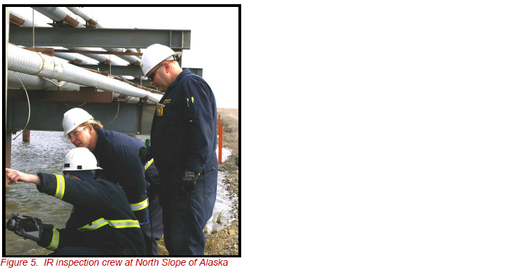
Figure 5 shows an IR crew inspecting a pipe. This photo was taken with the sun up, which is not the normal time to perform IR inspection. Figure 6 shows some typical IR images of water trapped in the foam insulation. IR inspection of each accessible area is repeated every 3 years.
COMPUTER MODEL
A mathematical computer model was developed specifically for this IR inspection application. This model provides an evaluation of the reliability of an IR inspection for detecting a significant quantity of water in the foam insulation for each specific pipe system at specific environmental conditions.
This thermal analysis is very complicated, as it involves numerous interdependent variables. These include the ambient temperature, the temperature of the liquid in the pipe, the ΔT between the pipe and the ambient temperature, the wind speed, the pipe diameter, the insulation thickness, the thermophysical properties of the materials, etc.
IR THEORY
IR inspection is a non-contact, nondestructive test method that provides a two dimensional map of the IR radiation coming from a surface. This IR map is related to the temperature distribution on the surface of the material. The thermal pattern may be analyzed to draw conclusions regarding what is under the surface of the material. IR does not “see” inside the wrap and does not detect water or corrosion directly.
The IR thermal pattern on the surface of the pipeline is caused by heat conducted from the warm inner pipe through the foam insulation to the outer metal wrap. However, the image may include reflections and conduction from various sources. These are discussed later.
HEAT TRANSFER-CONDUCTION
Thermal conductivity (K) is a steady-state thermophysical property of materials. When heat is flowing through a material, a temperature difference (ΔT) will be established between the hot side and the cold side. The heat flow can change and the ΔT may change, but K will not, except as a function of temperature.
As an example, consider a foam insulated pipe with oil in it at 150oF and an outside temperature of 30oF. The ΔT is 120oF and this will determine the heat flow (loss) through the foam insulation. If the original foam were replaced with another foam whose K is twice as high as the original foam, the ΔT will remain approximately the same, but the heat flow (loss) will be twice as great.
When water permeates the foam, the trapped water creates a localized increase in K, which results in more heat being conducted through the water to the wrap. This produces an increased temperature on the wrap that indicates the presence of the water inside. The IR camera detects this as a relative warm area. The water also causes the fluid in the pipe to cool off a little more, though the effect on the fluid temperature is insignificant.
Metal has much higher thermal conductivity than foam, water and ice. The thermal conduction along the metal wrap will tend to “smear” the thermal pattern caused by the presence of water, making thermal indication appear slightly larger than the area of the water.
HEAT TRANSFER-RADIATION: EMISSIVITY AND REFLECTIONS
IR images of pipelines will sometimes show warm spots that are not caused by the presence of trapped water. This is generally caused by reflections. The protective wrap around the pipeline is galvanized steel and its emissivity is low when new. Metals generally have a low emissivity, which means they have a high reflectivity. The relationship is Emissivity + Reflectivity = 1. As the galvanized wrap weathers, it forms zinc oxide, and the emissivity increases to approximately 0.7. This results in a reflectivity of 0.3, which will allow significant reflections of IR energy from any source.
If the sun is up, solar radiation can be reflected off the wrap and this could be erroneously interpreted as a hot spot indicating water. Generally, reflections from the sun are on the upper part of the pipe, while water is found at the bottom. However, if there is water or snow on the ground, solar radiation can be reflected off the ground and onto the bottom of the pipe.
The IR image of an IR inspector can also be reflected off the wrap. The operators must understand that reflections may come from many sources and they must be able to determine whether an apparent hot spot is a reflection or an area of trapped water. It is best to perform IR inspections when the sun is down to prevent solar reflections off the wrap.
HEAT TRANSFER-FORCED CONVECTION
When a cold wind blows it will cool off the wrap and reduce the intensity of the warm spot (lateral ΔT) at the location of trapped water. If the wind is cold enough or fast enough, it will erase the signature of the trapped water and make it undetectable. This could result in a false negative finding, meaning that water could be present, but it would not be detected. The presence of high wind will result in an unreliable inspection. As a result, IR inspections are not performed when the wind speed is more than 7 mph.
ENVIRONMENTAL CONSIDERATIONS
In winter in Northern Alaska, the sun doesn’t come up for about two months, the temperature may reach –60 F (-51 C), and there are “white out” snowstorms and howling winds. Employees may be restricted to base in the worst conditions. At these low temperatures employees may only be allowed to work outside for 15 minutes at a time.
Conditions are not good for IR inspections, or IR inspectors. In summer the sun doesn’t set for about two months and the ambient temperature may be too warm to produce the ΔT necessary for successful IR inspections. Because of the restrictions on sunlight, ambient temperature, and ΔT in the IR procedure, IR inspections are usually performed in the spring and fall. During these seasons the nights are dark, but the ambient temperature is not prohibitively cold.
The recommended lower limit for the IR cameras used by KAM is 5 F (-15 C), so testing is not generally performed below that temperature. However, in temperatures colder than 5oF, the camera may be warmed up in a vehicle and then used outside briefly before it cools.
LIMITATIONS OF THE IR PROCEDURE
It is critical that the use of the IR procedure, the IR image interpretation and data analysis must be performed by well-trained, experienced, certified personnel.
The use of this IR method should be viewed as a “best effort” inspection, as there are limitations in the effectiveness of this IR procedure. Not all areas of all pipes can be inspected. Some pipes are not accessible to IR, and some areas may be accessible to IR but not to RT.
The IR procedure should be used as a relatively rapid qualitative “screening technique” to look for a heavy concentration of water in the foam insulation. After the detection of water by IR, further evaluation of the indication is performed with a quantitative NDT technique, generally radiography (RT). This will confirm the presence of water and can also detect wall thinning in the steel pipe.
This IR procedure is not effective under all environmental conditions. Adverse conditions can significantly reduce the probability of detection of positive indications and can increase the appearance of both false positive and false negative indications. In addition, this IR procedure may only be used with certain sizes and geometries of pipes, as predicted by the computer model.
The IR procedure includes a table of conditions under which IR inspections may be performed. Guidelines are provided by the computer model.
IR inspections are not permitted under specific limitations or combinations of the following.
- Ambient temperature
- Delta temperature (ΔT)
- Pipe geometry (outer diameter, inner pipe diameter, insulation thickness)
- Wind speed
- Precipitation (rain or snow) or water on pipes
- Solar input
- Distance to pipe: generally not more than 30 feet, depending on lens used
CONCLUSIONS
- KAM is using IR as a primary inspection method to find water trapped in insulated pipelines to prevent CUI and pipeline leakage in Alaska.
- The KAM IR program has been successful in reducing the probability of CUI causing leakage. 3. IR evaluation to detect water trapped in insulation is subjective and operator dependent. 4. Operators must be knowledgeable, well-trained, and they must have a lot of experience. 5. No industry-wide standards or procedures have been found for the IR inspection of pipelines or the detection of water trapped in pipeline insulation.
- No company procedures for this have been found in open sources.
- Many companies are using IR to evaluate insulated pipes carrying steam, chemicals, cooling fluids, and refrigerated fluids such as liquid propane, and liquid natural gas. References for these applications are included in the bibliography.
BIBLIOGRAPHY
BOOKS:
- Corrosion Under Insulation, (CUI) guidelines (EF 55), edited by S. (Dr. Stefan) Winnik, ExxonMobil, UK, (March 2008). See references to IR on pages 46, 51 and 136-137
- Corrosion Under Wet Thermal Insulation, edited by Warren I. Pollock and C. N. Steely (Jan. 1990). Proceedings of a conference. See references to IR on pages 39, 41, 49.
- Infrared Handbook, Volume 1, Principles and Practice, British Institute of Non-Destructive Testing, Norman J. Walker, 2004 ISBN 0903 132 33 8
- Infrared Handbook, Volume 2, Applications, British Institute of Non-destructive Testing, A. (Andrew) N. Nowicki, 2004 ISBN 0903 132 32 x
TECHNICAL ARTICLES AND PAPERS:
- IR Evaluation of Foam Insulated Pipelines to Detect Trapped Water that Could Cause Corrosion Under Insulation (CUI), D. Burleigh, A. Sanders, Extended abstract for ASNT ICPIIT (International Chemical and Petroleum Industry Inspection Technology) XII Conference Houston TX, June 8-11, 2011
- Thermographic identification of Wetted Insulation on Pipelines in the Arctic Oilfields. J.J. Miles, A.L. Dahlquist, L. C. Dash, SPIE Thermosense XXVIII Conference, 2006 Orlando FL, Proceedings Volume 6205 (62051H, pages 1-12)
- Using IR Surveys to Locate Corrosion Under Wet Insulation, David Hatfield, DuPont Dow Elastomers, Proceedings of FLIR Inframation Conference 2004, ITC 104 A 2004-07-27.
- Inspection Techniques for Detecting Corrosion Under Insulation, Michael Twomey, CONAM Inspection Inc. Copyright 1997 by the ASNT (American Society for Nondestructive Testing) 5. Use of microwaves for the Detection of Corrosion Under Insulation, R. E. Jones et Al. Review of Progress in Quantitative Nondestructive Evaluation (QNDE), Volume 1211, P. 1373-1380, 2010 6. Strategies to Prevent Corrosion Under Insulation in Petrochemical Industry Piping, Brian J. Fitzgerald, Peter Lazar, Robert M. Kay, and Stefan Winnik, ExxonMobil Chemical, CORROSION 2003, March, 2003, San Diego CA
- Proceedings from a conference: Corrosion Under Insulation (CUI) - Have you a Problem? 14 Jan 2004, Sheffield, UK
- Infrared Thermography in BP Amoco—Petrochemical Applications, John Nyholt, BP Amoco Upstream Technology Group.
- Using IR on Insulated Pipe System, Al Ohlinger, Chevron USA. Proceedings of FLIR Inframation Conference 2005. ITC 108 A 2005–06-01.
- Corrosion Monitoring of Non-Common Carrier North Slope Pipelines. Technical Analysis of BP Exploration (Alaska) Inc. – Commitment to Corrosion Monitoring Year 2000 for Greater Prudhoe Bay, Endicott, Badami, and Milne Point. Coffman Engineers. January 2002. ADEC contract 18-600-02.
- Inspection, Maintenance and Prevention of Corrosion of Piping under Thermal Insulation, Kobrin, and Moniz, First International Symposium on Process Industry Piping, December 14-17, 1993, Orlando FL, sponsored by NACE International and MTI
ABOUT THE AUTHOR
Mr. Burleigh has a B.S and M.S. in Physics from Penn State. He spent 30 years in the Aerospace industry in R&D, Testing, and NDT development. His has worked extensively in the development of IR NDT of composite materials for aerospace structures.
Related Articles
-
 Thermography Fundamentals
Know Your Subject Matter
Read the Story -
 Electrical/Mechanical
Five Years of Infrared Results at CNA – March 2005 through June 2010
Read the Story -
 Electrical/Mechanical
Identifying Gear Alignment and Lubrication Concerns
Read the Story