Optics of Glass Fronts of Buildings: The Science of Skyscraper “Death Rays”
InfraMation 2011 Application Paper Submission
K.-P. Möllmann, M. Vollmer, University of Applied Sciences, Brandenburg/Germany
M. Winburn, Thermal Insight, Las Vegas, Nevada
ABSTRACT
Optical phenomena due to reflections from glass fronts of buildings are discussed. Such effects can be detected for windows in planar walls, however, the mirrored windows of curved building fronts lead to much more pronounced results. The paper discusses simulations and experiments using sunlight and cylindrical mirrors. In addition, a scale model (1:200) similar to a well-known large building in Las Vegas was made and its facade covered with mirror foil. Reflection of sun light leads to caustics with focal areas of very high irradiance, depending on orientation of building and position of the sun. Thermal effects could easily be detected.
INTRODUCTION
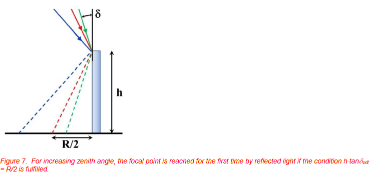
SkyscraperFor simplicity, we first assume light with azimuth angle 0°, i.e. which is incident in the plane defined by the light direction and the optical axis as indicated by Figure 6. If the zenith angle is too small (high sun elevation), the focal point cannot be reached by any reflected light. The focal point can be reached for the first time with increasing if the condition h·tan crit =R/2 is fulfilled (Figure 7). This defines, for given geometry (h, R), the respective zenith angle crit. This condition is special for cylindrical mirrors as will be seen below when discussing the respective caustics. s are masterpieces of architecture. In the first half of the 20th century these huge buildings relied upon rectangular geometry and featured walls whose window area was much smaller than the stone wall surrounding it. With the last few decades, modern buildings are getting fancy regarding shape as well as the materials of the building fronts. Many new building fronts involve architectural glass which means that more or less the whole front of a building is made of shiny, reflective surfaces. One technical reason for using such glass is to prevent intense thermal load inside the building during summer. On the one hand, this leads to spectacular views and fascinating sights in the distance. On the other hand, reflections of sunlight can cause disturbing and blinding light spots. This nuisance factor is already well known from any building with flat windows which act as mirrors (of a much lower reflectivity than typical bathroom mirrors). In optics, it is well known that the irradiance of reflected light from a convexly-shaped curved mirror can be much higher at certain spots, the focal points, than from a planar mirror of the same size since curved mirrors can focus light similarly to convex lenses from magnifying glasses (e.g. [1]).
This general optical phenomenon due to convex curved mirrors also applies to the huge glass fronts of curved-shape skyscrapers. The situation is most pronounced if the building front is facing south (if located in the northern hemisphere) and the location is at low latitude such that attenuation of sun light due to air mass is small in summer. In recent years, several buildings, and one building in particular, the Vdara in Las Vegas, have been getting famous for this optical phenomena (e.g. [2]). Due to the focussing of sun light by the huge mirror-like building surface, focal spots in the pool area in front of the building were formed, which caused sun burn and melting of plastic bags. The physics background of this phenomenon is simple and can be visualized by modelling or by experiments taking into account the daily path of the sun in various seasons.
EFFECTS DUE TO NORMAL-SIZE PLANAR WINDOWS
Double pane windows consist of two glass panes which are separated by a volume filled with some inert gas (the light red color in Figure 1). Since the inner volume is air tight, the two glass panes are only parallel (i.e. the inner volume stays constant) if the ratio of outside pressure and temperature stays constant with respect to the manufacturing conditions of the window. Whenever this ratio changes, the inner pressure and, hence, the volume will change due to the elasticity of the glass panes. This can lead either to convex or concave surfaces of the window, i.e. the initially planar window can change into a nonplanar geometry (see Figure 1). If sun light is incident on such a window pane with convex shape, the reflected light from the two front surfaces behaves as if it is being reflected from a spherically-shaped mirror. If parallel light is incident on axis of spherical mirrors, light is focused to a focal point located at a distance of about R/2 if R is the radius of curvature of the surface [1]. Since windows are of rectangular rather than spherical shape, the deformation of the window panes will lead to at least a superposition of two radii of curvature and therefore the resulting focal point image will be distorted [3].
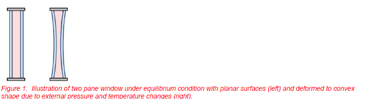
Figure 2 depicts some examples of window reflections. Sunlight is incident on windows in a 5 story office building on our campus. The reflections from the windows are projected onto the walls of a neighboring two story building. Figure 2/left depicts schematically the reflection of light from a window of the third floor towards the wall at ground level. The reflections of at least four windows (size 1.25m x 1.74m) can be seen (Figure 2/right), each of them being distorted differently. One of them, being observed closely by two people with an IR camera shows a rather sharp focus. Visual and IR images are shown enlarged in Figure 3. The windows responsible for the reflections could be easily identified by tilting the windows, which led to a displacement of the reflected light focus.
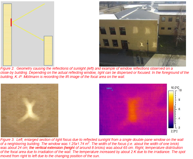
Whenever light from a large area is focused to a much smaller area, irradiance increases with regard to the adjacent wall regions that lie in shadow and are only illuminated by diffusely scattered sunlight. As a result, the focal area equilibrium temperature will increase. The effect due to a single window focusing sun light via
reflection was analyzed with an LW IR camera pointed at the wall area. The result is shown in Figure 3/right. The temperature increase at the center of the focal area amounted to about 2K with regard to the shadow regions of the wall. The situation changes quite rapidly: the reflection was at a distance of about 30 m from the window. Within one minute, the sun moved by about (1/4°) leading to a change of (1/2°) of the reflected beam. This corresponds to a distance of about 25cm on the wall, covered within one minute. Therefore, transient effects of heat conduction tend to decrease the temperature increase.
A very rough estimate can help to understand the effect. The 2 m2 window has about 4% reflectivity from each surface. Two surfaces contribute to the focusing, which means that for a sunny day of, say, 1000W/m2 and normal incidence at sea level, about 8% will be reflected towards the focus. The sun was about 40° in the sky which reduces the irradiation for vertically-oriented windows to about 77%, giving a total of the reflected radiation forming the focal area of 0.08 0.77 800 W/m2 2m2 ≈ 125W. This radiation is illuminating the focal area of about 0.25 0.65m2 = 0.16m2. Taking into account the areas of surrounding optical features, we assume an area of, say 0.3m2to which the radiation is focused. This leads to an irradiance of 125W/0.3m2 ≈ 420W/m2 which – as expected from the only 2K temperature rise - is still much less than if the wall would be in full sun light.
The argument was checked by measuring irradiances on a sunny day with a clear blue sky. The direct irradiance was about 1000 W/m2, the diffuse irradiance in the shadow region outside of the reflected light focus was ≈ 150 W/m2 and the maximum irradiance in the focus was up to 650 W/m2. Setting aside the diffusely scattered light contribution, the increase of irradiance within the focus of about 500 W/m2 is in agreement with the estimate of 420W/m2. For one window with very good focus, i.e. small focal area, we could even reach 900 W/m2, i.e. almost the direct sun irradiance!
Obviously, single windows of 2m2 size can easily lead to observable visual effects and temperature increases in the focal areas of several K. If the windows are coated such that they reflect more light, the effect is much more pronounced. Imagine an array of such reflecting surfaces which all aim at a common focal area. This can obviously lead to very high irradiances and respective thermal effects. As a matter of fact, the idea behind this is quite ancient. According to a legend, Archimedes should have used a large array of mirrors to burn an enemy fleet anchoring near Syracuse [4]. A similar modern application are solar tower power plants where light is focused from a large number of mirrors onto a focal area where temperatures of several thousand K can be reached with prototypes of up to 20 MW built in Sevilla and Almeria in Spain [5].
The above two applications – burning a fleet or generating electric power – utilize the positioning of mirrors on purpose. It is, however, sometimes also possible to have similar phenomena due to unwanted and unplanned situations for example in modern skyscrapers with shiny glass facades.
OPTICS OF SPHERICAL, PARABOLIC, AND HALF-CYCLINDRICAL MIRRORS
The Cause of Caustics
Roughly speaking, reflecting surfaces can be divided into those that give perfect images and those that do not. Consider a curved mirror and parallel light which is incident parallel to the symmetry axis of the mirror. Figure 4 depicts two possible realizations, first, spherical mirrors (left), and second, parabolic mirrors (right).
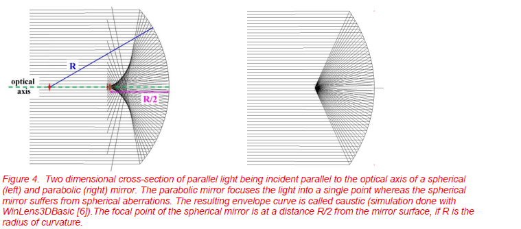
A mirror is said to produce ideal (or perfect) image if all of the incident parallel light passes through a single point after being reflected by the mirror. This holds for some aspherical mirrors such as the parabolic one, but it does not for the spherical mirror. The only law to be used in the constructions is the law of reflection, i.e. the angle of incidence is equal to the angle of the reflected ray with respect to the surface normal. Here light is treated as rays, whose direction of propagation is defined by straight lines.
The (horizontal) symmetry axis of a spherical mirror, defined by the vertex of the surface (the surface point on the mirror at the right edge) and the center of curvature of the surface (radius R) is called optical axis. If parallel light is incident and furthermore parallel to the optical axis, a focal point is formed at the middle between center and vertex point, i.e. at a distance R/2 from the vertex (similarly, the optical axis of a paraboloid is passing through its vertex and its focal point).
From Figure 4, one can see another feature arising from the construction of reflected light rays of the spherical mirror. One can define a so called caustic which is the three dimensional enveloping curve or surface of reflected light rays. For the spherical mirror in Figure 4, the caustic is the two dimensional projection on the drawing plane. It is seen as curved section with higher density of light rays. Since the density of reflected light rays is a measure of irradiance at a given location, the enveloping curves, i.e., the caustics always represent locations where the irradiance is higher with regard to adjacent locations! In contrast to the spherical mirror with its curved caustics, the parabolic mirror with illumination parallel to the optical axis, has a single focal point and does not have an enveloping curve since the various light rays do not overlap, as for the spherical mirror. Caustics are related to aberrations, and mirrors producing perfect images do not have aberrations.
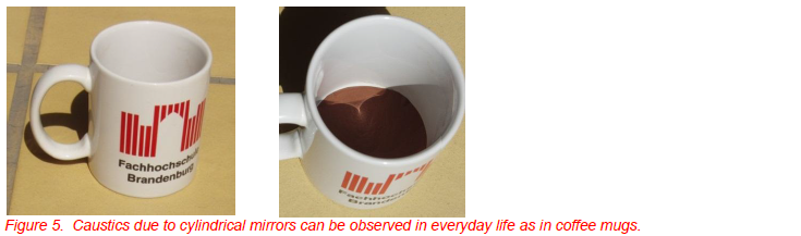
The shape of caustics is well-defined and characteristic for the geometry of the reflecting surfaces (or if refracting objects such as lenses etc. are used of their respective geometry). General theoretical treatments of caustics for various geometries can be found in the literature (e.g. [7, 8]). Here we will focus on caustics of cylindrical mirrors since these are similar to situations encountered in some modern buildings. For much smaller sizes, the respective phenomena are well known, e.g. when observing optics of smaller cylinders such as tea or coffee cups or mugs (see e.g. [9-12]).
Caustics of Cylindrical Mirrors for Azimuth Angle 0°
Figure 5 depicts some photos of the caustics of a coffee mug. The mug had an inner height of 8cm and a radius of curvature of 3.7cm. A brown paper circle lined the bottom of the mug to serve as projection screen. The right image shows the caustic for a solar elevation of 54°.
In order to better understand the optical phenomena upon reflection from cylindrical mirrors, in particular of the respective caustics, a number of simulations and simple lab experiments have been performed. Theoretically, a cylindrical mirror is described by its height h, its radius of curvature R, and the direction of the optical axis (for cylinders of given height, the optical axis just defines a direction, its height in the vertical direction along the symmetry axis of the cylinder is not well-defined). For light which is parallel to the optical axis, a focal line is found at a distance of R/2 (see Figure 4).
Incident light is characterized by its zenith angle (or its respective solar elevation angle s= 90°- ) and the azimuth angle with respect to the optical axis of the mirror.
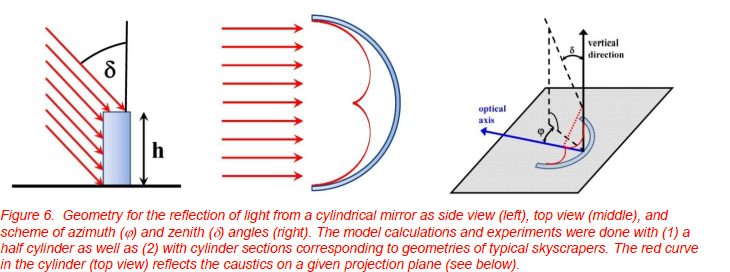
For simplicity, we first assume light with azimuth angle 0°, i.e. which is incident in the plane defined by the light direction and the optical axis as indicated by Figure 6. If the zenith angle is too small (high sun elevation), the focal point cannot be reached by any reflected light. The focal point can be reached for the first time with increasing if the condition h·tan crit =R/2 is fulfilled (Figure 7). This defines, for given geometry (h, R), the respective zenith angle crit. This condition is special for cylindrical mirrors as will be seen below when discussing the respective caustics.
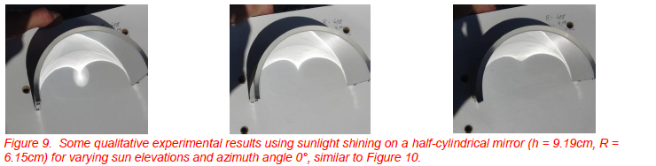
The caustics of cylindrical mirrors have been studied theoretically using the freeware program “persistence of vision raytracer” (POV) [13] as well as experimentally using half cylinders (here h = 9.19cm, R = 6.15cm) whose surfaces were covered by mirror foil with (wavelength-dependent specular) reflectivity R ≈ 0.65 to 0.7 in the visible spectral range. Figure 8 shows some results from the simulations with a vertically-oriented half cylinder and parallel light (in the experiments sunlight was used, therefore the light source will be denoted as sun from now on) being incident with azimuth angle = 0° and varying sun elevation s = 90° - is the zenith angle defined in Figure 6). A section of the three dimensional caustic is projected on the two dimensional horizontal surface at the bottom of the cylinder. Depending on the height of this surface, different parts of the caustic are monitored.
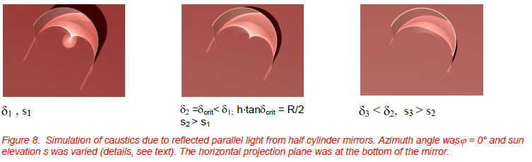
If the sun was in the zenith, there could be no reflection at all. For increasing zenith angle (from right to left), the respective shadow from the cylinder can be seen. For small , the reflected light starts to move away from the vertex into the direction of the focal point (right). Once, the zenith angle has reached the value for the condition h·tan crit = R/2, the focal point is formed (situation for 2). For still larger , i.e. lower sun elevations, the irradiance within the focal point decreases as a circle starts to form around the focus (situation for 1), spreading the light into a larger area.
Comparing the three images visually, the one with crit, producing the focal point seems to have the largest irradiance within a small area. For smaller angles , the caustic moves more towards the mirror with lower irradiance than within the focal point and for larger , the focal area increases, which again means that the
reflected light irradiance decreases. This means that for any cylindrical mirror, there is an optimum condition where the irradiance within the focal area, defined by the intersection of the caustics with the respective plane of observation, is highest (see below).
Figure 9 shows some experimental results. The angle of observation was different in order to avoid blocking the sun light with the camera, yet the caustics qualitatively look very similar to the simulation.
Realistic Sun Elevation and Azimuth for a Las Vegas Summer Day
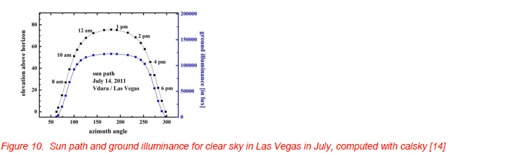
Obviously, in a building acting as a mirror, its orientation with respect to the earth is fixed which means that over the course of a day, not only the sun elevation, but also the azimuth angle will change with date and time of the day. There are a variety of possible programs available to compute the exact sun position as function of location on earth, date, and time, e.g. [14]. Figure 10 depicts an example of the sun‟s path, i.e. sun elevation as function of time – or as plotted here as function of azimuth angle. In addition, the ground illuminance (given in lm/m2) is shown as blue curve related the right axis. For this example, a summer day, July 14th, 2011, was arbitrarily chosen for a location in Las Vegas. A number of points on the plot have been marked with their respective times of day. Obviously, sun elevation can reach values above 70° for at least 2 hours with quite large respective changes of more than 80° of the azimuth angle. As a consequence, one must study in detail what will happen to the caustics if the azimuth angle changes, i.e. if sun light is incident obliquely.
Caustics of Cylindrical Mirrors for Varying Azimuth Angle
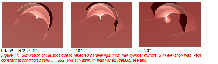
For simplicity, the sun elevation is kept constant and only effects of changing azimuth angle are considered. Figure 11 depicts some simulation results obtained with the POV program [13] for a sun elevation s = 90° - crit which corresponds to the condition of just hitting the focal point. While changing , the caustic pattern shifts horizontally while simultaneously changing in a similar way as if solar elevation would decrease for constant azimuth angle (compare Figure 8). This means that the irradiance patterns at various locations on the projection screen change and maximum values decrease. Assuming for the moment that the condition h tan crit = R/2 would refer to sun elevation with maximum irradiance, it is obvious that any change of azimuth angle will decrease irradiance. Since, in addition, sun elevation would also drop slightly (compare Figure 10) there would be an additional drop in irradiance due to the pattern of Figure 8. The quantitative question of how much the irradiance changes is more complex and will be treated in the section that follows on quantitative estimates for the optics of curved buildings.
OPTICS OF CURVED BUILDINGS: SECTIONS OF CYLINDRICAL MIRRORS
Three main questions arise from the findings of cylindrical mirrors for building optics. First, what are the differences regarding the caustics when having only cylindrical sections are present (as usual for buildings) rather than half cylinders? In Figures 8 and 11 Second, what kind or irradiance increase with respect to normal illumination of a surface can be achieved by the reflection near the focus points of the caustic? Third, are there irradiance levels above which unwanted thermal changes of objects on the projection plane can be caused? If so, one must discuss measures to reduce irradiances in order to avoid such effects.
Caustics of Realistic Building-Type Sections of Cylindrical Mirrors
Whenever mirrors are formed from small sections of cylindrical mirrors, the caustics change. Qualitatively the change can already be guessed from the light ray graph with the spherical mirror in Figure 4. The nonlinear, i.e. curved shape of the enveloping curve is mainly due to the outermost rays. If only rays close to the optical axis are used, the spherical aberrations are drastically reduced and the so called paraxial approximation yields the same results as the parabolic mirror. Therefore, one can expect that the reflected light rays will be limited more or less by a triangularly-shaped area. This is indeed the case as is shown in Figure 12, which depicts a POV simulation for a cylinder section which more or less resembles the geometry of a typical modern architectural building. Similar to Figure 8, azimuth was set to 0° and sun elevation was changed.
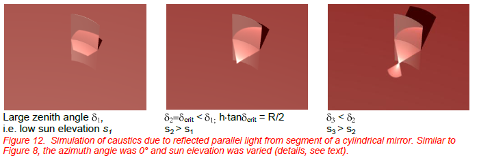
As expected, more or less triangular-shaped sections of the previous caustic are present; at the standard condition, the focal point is reached and for lower sun positions, the loop contributions decrease the irradiance due to a spreading of the light into a larger area.
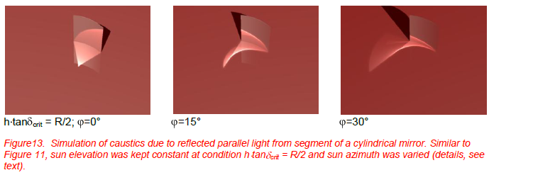
Similarly, Figure 13 depicts the situation of a cylindrical mirror section with constant elevation, but varying azimuth angle. Due to the much smaller reflecting area, however, the caustics look dramatically different compared to Figure 11, which gave results for the half cylindrical mirror using similar conditions. Still pronounced caustic features can be seen and this means there are areas with a much higher irradiance compared to irradiance without reflections.
Quantitative Estimates
In order to quantitatively estimate the changes of irradiance in the focal areas with respect to normal illumination of a horizontal surface (i.e., without any reflection contributions), some quantitative simulations with the commercial optical simulation software Zemax [15] as well as some measurements with the cylindrical mirrors were performed.
The theoretical model was scaled 1:1000 with regard to a realistic large building (see the section on Experimental Models below), i.e. in the simulation mirror dimensions were given in mm. The light source was modeled as parallel light with a total power of 1W within a circular area of 50mm radius. The irradiance on a horizontal plane in front of the mirror is computed quantitatively. For the plot of the caustic and irradiance due to the reflected as well as unperturbed light rays hitting the surface, a total of five million light rays within the light circle were followed using ray tracing procedures.
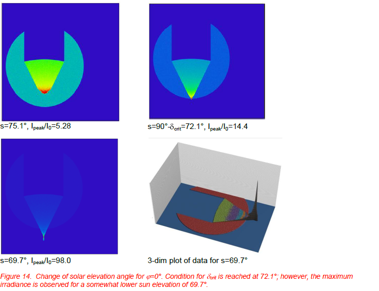
Figure14 depicts results for a section of a cylindrical mirror with radius of curvature of 160mm and a width of the illuminated section of about Rsun = 50mm. The azimuth angle was = 0° and the sun elevation was varied. The color scale for irradiance varies from image to image; it extends from zero to the respective peak irradiance in W/cm2. The irradiance of the light source at the horizontal projection plane for any given sun elevation without reflections from the mirror was computed from the known normal incidence irradiance (1W/( Rsun2) = 1.27·10-2 W/cm2).
Figure 14 illustrates that for azimuth angle =0°, the maximum irradiance on a horizontal projection plane at the lower end of the cylindrical mirror change does not occur for sun elevation s=90°- crit, but rather at a somewhat smaller elevation, here 69.7°. This is understandable since the condition for crit means that only the light hitting the upper part of the mirror is able to reach the focal point. For lower sun elevation, a greater area of the mirror can contribute to reflected light irradiance within the focal area. For still lower elevations, the decrease due to the second epicycle structure (see Figure 8) will overcome this effect. We found a maximum irradiance which is about a factor of 100 higher than the respective irradiance on the same surface without reflection from the mirror. The three-dimensional plot (right) gives another representation of the maximum irradiance condition in order to better visualize the focusing effect.
If – as usual in reality – azimuth and zenith angle change during a day (e.g. according to Figure 10), the caustics shift and the irradiance patterns and maximum values change similar to Figures 11 and 13. Respective simulations resulted in enhancement factors of typically larger than 20 for conditions that extend over a time scale of several hours (Figure 10).
Irradiance was also measured for various models such as sections of cylindrical mirrors as well as a scale model of a building complex (see the section that follows on Experimental Modeling). Within the focal areas, irradiance increases by a factor of 20 to 40 could be easily observed, which is in agreement with the theoretical predictions. The conclusion from qualitative and quantitative simulations as well as experiments are as follows: first, irradiance may easily increase by a factor up to 100 for optimum geometry; second, enhancements of more than a factor of 20 seem easily possible for a few hours. The respective areas can easily amount to several m2.
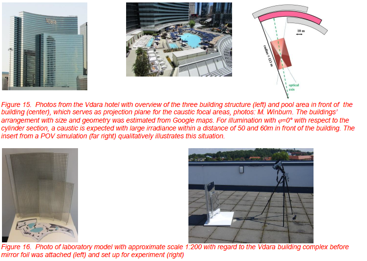
Experimental Models
So far we have studied caustics and areas with large irradiance due to reflected light from cylindrically-shaped mirrors. The respective phenomena have become famous in one building in particular, the Vdara in Las Vegas (e.g. [2], see Figure 15). Due to the focusing of sunlight by the huge mirror-like building surface, focal spots in the pool area in front of the building were formed, which were reported to cause sunburn and to melt plastic bags. In order to investigate the thermal effects due to light focusing of such a building, we prepared a building model with a scale 1: 200 (Figure 16).
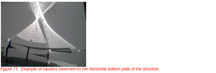
The model was made of a wire mesh structure as shown in the diagram of Figure 15/bottom. A mirror foil with typical specular reflection between 65 and 70% in the visible spectral range was attached to the structure, creating portions of cylindrical mirrors. The caustic and respective thermal effects can be observed on the horizontal plate at ground level of the structure. This horizontal area can be covered by piece of paper indicating a pool area or whatever is needed.
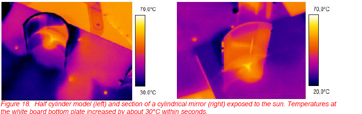
This model was used in sunlight under clear skies in June of 2011 in Brandenburg. Figure 17 shows an example of the observed caustics. Depending on sun elevation and azimuth angle, each of the two mirror segments contributed differently. All of the observed caustics were consistent with the theoretical simulation
Thermal Effects in Focal Areas
The enhancement of irradiance in the focal areas led to interesting observable thermal phenomena. For example, we used the horizontal white, wooden projection plane of the model for the half cylindrical mirror used in Figure 9 to illustrate caustics as well as a section of a cylindrical mirror. Figure 18 depicts the results recorded with a LW IR camera. Within seconds, the surface temperature rose by more than 30°C.
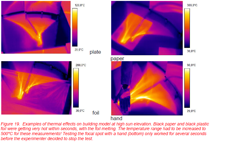
Obviously, the maximum observable temperature rise and the time constant depend on: the irradiance which is available, the ability to absorb sun radiation of the objects, and the heat capacity and heat conductivity of the objects as well as their ability to lose energy via conduction, convection and radiation [16, 17]. The effect can be optimized by using black cardboard or plastic foil. Figure 19 depicts results for these materials obtained with our building model. The 1.5 cm-thick wooden bottom plate reached temperatures of up to 110°C after a few minutes. This maximum occurred when the caustics of the two front mirrors overlapped.
The temperature of a thin sheet of black paper rose to more than 250°C within seconds! A black plastic foil could not even reach equilibrium temperatures before starting to melt within seconds at a temperature of only 200 °C. Obviously, it is not advisable to have one‟s skin exposed for long within these focal areas. Keeping in mind that reflected sun light also includes UV radiation, it is obvious that intense irradiation in such focal areas could cause enhanced tanning and sunburn would occur in a much shorter time period.
CONCLUSIONS
We have investigated caustics and respective enhancement of irradiance on horizontal surfaces due to reflection of sun light with cylindrically-shaped mirrors. Simulations show caustic features which can be easily verified in experiments. For suitable geometry, maximum irradiance can be a factor of 100 larger than for normal conditions without reflections. As a consequence, the strong enhancement of irradiance depends on the sun elevation and azimuth angle and thus changes during a day. The effects were studied experimentally using a building model as well as various cylindrical mirrors. Thermal effects within areas of high irradiance depend on the object under study. Paper can get very hot and plastic bags can easily melt in the focal areas. Skin exposure also leads to temperature rises beyond the point of feeling comfortable.
In order to avoid such effects for buildings acting as mirrors, one may reduce the specular reflectivity of the mirrors, e.g. by increasing the diffuse scattering contribution by making the mirror surfaces rough or adding a rough foil. Alternatively, the orientation of individual mirrors (e.g. window sections) may be modified such that not all individual mirrors focus the light onto the same spot.
We expect the occurrence of this optical phenomenon to increase. This is not only due to the desire for an appealing appearance, but also to the increasing importance of energy efficiency of buildings. The latter promotes the use of architectural glass with typical reflectivities >20% in the visible spectral range. Therefore, we recommend that - for new buildings - one should make a careful analysis of sun paths and building orientation in advance and maybe change the orientation of the whole assembly accordingly. For existing buildings, there is the additional option to provide shade regions in the critical areas.
REFERENCES:
[1] E. Hecht, Optics, 4th. Ed. Addison Wesley (2002)
[2] http://www.dailymail.co.uk/news/article-1315978/Las-Vegas-hotel-death-ray-leaves-guests-severe burns.html
[3] H. J. Schlichting, Lichtkreuze in Lichtkreisen, Der mathematische und naturwissenschaftliche Unterricht (MNU) 57/8 467–474 (2004)
[4] S. Semenchinsky, Focusing on the fleet – Archimedean smoke and mirrors, Quantum, p. 28-30 (September/October 1993) published by NSTA and Springer
[5] W. Vogel, H. Kalb, Large-Scale Solar Thermal Power: Technologies, Costs and Development, Wiley (2010)
[6] WinLens is available as freeware basic version (reduced options) or as full program from http://www.winlens.de/
[7] M.V. Berry, C. Upstill, Catastrophe optics: morphologies of caustics and their diffraction patterns, Progr. in Optics XVIII, North Holland (1980)
[8] P.S. Theocaris, Properties of caustics from conic reflectors, 1. Meridional rays, Appl. Opt. 16, 1705 - 1716 (1977)
[9] C. Ucke, C. Engelhardt, Playing with caustic phenomena, p. 440-446 in Proc. GIREP/ICPE conference „New ways in physics teaching‟, Ljubljana 21.-27.8.1996
[10] B. J. Loe, N. Beagley, The Coffee Cup Caustic for Calculus Students, The College Mathematics Journal, 28/4, 277-284 (1997)
[11] A.D. McIntosh, An equation for the caustic curve, Phys. Ed. 25, 171-173 (1990) [12] P. Ferraro, What a caustic, The Physics Teacher 34, 572-573 (1996)
[13] http://www.povray.org/
[14] www.calsky.com
[15] Zemax is a professional optical simulation software, available from http://www.zemax.com/ [16] M. Vollmer, K.-P. Möllmann, Infrared Thermal Imaging: Fundamentals, Research and Applications, Wiley (2010)
[17] M. Vollmer, Newton´s law of cooling revisited, Eur. J. Phys. 30, 1063-1084 (2009)
ACKNOWLEDGEMENTS
We want to thank Steffen Ludwig for help with Zemax simulations, as well as Frank Pinno, Thomas Trull, and Detlef Karstädt for help with some of the experiments.
ABOUT THE AUTHORS
K.-P. Möllmann studied physics in Halle and Berlin, receiving his PhD in 1983 and Habilitation (1989) in solid state physics, in particular in the development of HgCdTe infrared detectors. Since 1994, he has been a professor of physics at the University of Applied Sciences, in Brandenburg, Germany. He has worked in infrared thermal imaging, pyrometry, thin film, and MEMS technology and is a Level II Certified Thermographer.
Michael Vollmer studied physics in Heidelberg, Germany, receiving a PhD (1986) and Habilitation (1991) in optical spectroscopy of metal clusters. Since 1994, he has been a professor of physics at the University of Applied Sciences in Brandenburg/Germany, working in the fields of infrared thermal imaging, spectroscopy, atmospheric optics, and didactics of physics. He is a Level II Certified Thermographer.
Michael Winburn studied at Bonanza High School and Universal Technical Institute. He founded Thermal Insight in April 2007 and became the president of the company. He is a Level II Certified Thermographer.
Related Articles
-
 Thermography Fundamentals
Know Your Subject Matter
Read the Story -
 Electrical/Mechanical
Five Years of Infrared Results at CNA – March 2005 through June 2010
Read the Story -
 Electrical/Mechanical
Identifying Gear Alignment and Lubrication Concerns
Read the Story