Thermography for Building Science Applications
InfraMation 2011 Application Paper Submission
Scott Wood
Scott Wood Associates, LLC.
ABSTRACT
In building science, the knowledge of Heat, Air, Moisture (liquid), and Moisture (vapor) flows (HAMM) within the building enclosure can help investigators to understand and explain issues relating to comfort, energy use, sustainability, and basic building performance. To investigate a building thoroughly, examining a building’s HAMM is essential, but how can we "see" heat, air, and moisture flows? This paper discusses four building barriers to HAMM using thermal images to demonstrate how easily infrared thermography allows the investigator to "see" heat, air and moisture flows.
INTRODUCTION
Buildings, some many thousands of years old, were first created to provide inhabitants protection from the elements. Today, with the majority of our time spent indoors, we demand comfort and fine-grained control of that environment. We are also experiencing increased energy costs requiring a closer look at how to control energy loss. According to building science, to achieve this objective, we need to control the factors affecting the chemical, physical, and biological reactions that occur within the building, or to sum it up, control energy flow. To control the air and moisture flows within and through the building or enclosure, we place barriers to heat ,air, bulk moisture, and moisture vapor flow (HAMM).
Infrared thermography creates a visual representation of the electromagnetic energy emanating from the surface. This energy image allows the trained user to look at and analyze energy flows within the building. With a good understanding of building sciences and infrared thermography, the processes of the energy flow (HAMM) in the building are clear.
WHAT IS HAMM?
The controlling factors for physical, chemical, and biological reactions are heat, air and moisture. We divide moisture into two categories: bulk or liquid water and vapor, different enough from one another to require separate controlling methods. Through the use of heat, air, and moisture barriers (or retarders for some), we can reduce the energy flow through the enclosure, thus reducing the environmental reactions that can degrade the structure and in the process, also create a comfortable living environment for the inhabitants.
Heat Flow
The transfer or movement of heat energy is achieved by three different modes; radiation, conduction, and convection (see Figure 1). It is important to understand these modes of heat transfer in order to understand what is required to effectively block heat’s movement.
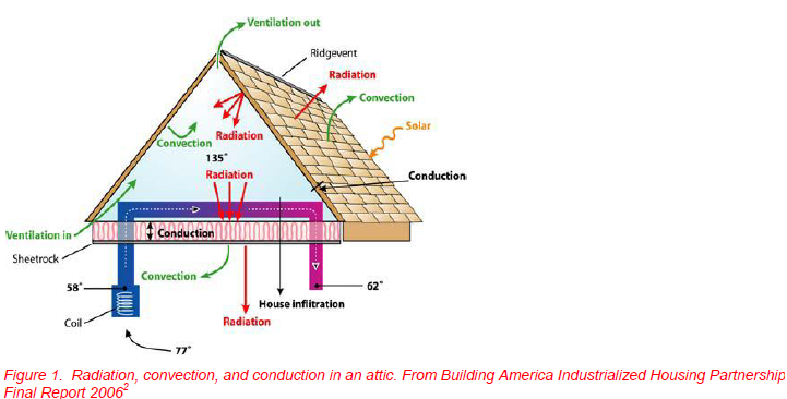
Radiation heat transfer is the transfer of energy as infrared electromagnetic radiation that travels from its source though space (air) or infrared transparent materials (such as the typical germanium lens of an infrared imager or thin polyethylene). This energy is absorbed by opaque solids such as the building’s roof and walls. All objects radiate electromagnetic energy at varying degrees depending on their temperature. It is this radiation from building surfaces that an infrared camera detects and makes visible as a thermogram or infrared image.
The most common form of heat transfer studied in building applications is conduction. Here, heat energy is transferred from molecule to molecule of a substance, moving from warmer areas to the cool areas. An building insulated with fiberglass, cellulose, or polyurethane foam can slow conductive heat transfer. The R value is a common measurement used to express the heat transfer rates within building components (especially insulation).
The third mode of heat transfer is convection which occurs in fluids such as water and air. This is the most neglected and misunderstood heat transfer method in building design and construction. It is sometimes referred to as air movement when discussed in building applications. Air movement is now being considered an important source of heat loss through the building’s enclosure. An air barrier and pressure testing is now required in many of the new building codes. The U.S. Department of Energy reports that up to 40% of the energy used by buildings for heating and cooling is wasted through uncontrolled air leakage.
It should be pointed out that slowing heat transfer through the building and minimizing the energy flow, we have reduced heating and cooling costs, but have also decreased the ability of building to dry out.
Air Flow
The uncontrolled movement of air through the building enclosure (as mentioned above) increases energy movement throughout the building, increasing energy consumption and operating costs. It is also known that moisture vapor is transported by air movement much more effectively than vapor diffusion and is a primary mechanism for water transport throughout the building enclosure. Air flow can only be effectively blocked with a continuous air barrier. To be effective, the air barrier must be continuous or completely surrounding all six sides of the building. If insulating materials such as fiberglass or cellulose are used to block conductive heat transfer, the air barrier needs to be included within the area of insulation. This air barrier blocks convective heat transfer as well as air-transported moisture. Careful consideration in detailing and installation at the transitions between walls or between the walls, roof, and floor to insure no air movement is important for a successful air barrier.
Moisture (Bulk) Flow
Moisture damage in buildings accounts for more than three-quarters of all building defect losses. It is essential that the building’s cladding and moisture barrier protect the building from intruding moisture. Roofing, wall, and flashing details are important for providing effective control for moisture intrusion. In many wall systems, however, it is not the cladding that ultimately blocks water intrusion, but the secondary moisture barrier internal to the system and the flashing details.
Moisture (Vapor) Flow
Of the four controlling factors of HAMM, vapor control is the most misunderstood, and, luckily, the least likely moisture flow to cause problems. Movement of moisture through vapor diffusion can be controlled with vapor retarding materials as simple as latex paint. Inappropriate installation of a vapor barrier or the inclusion of multiple vapor barriers in a wall or roof system can lead to moisture damage. In some cases, a vapor barrier can be installed as an air barrier, but must be designed and installed with care. Most vapor barriers constructed of polyethylene are not continuous and therefore not air barriers.
Building Them Correctly
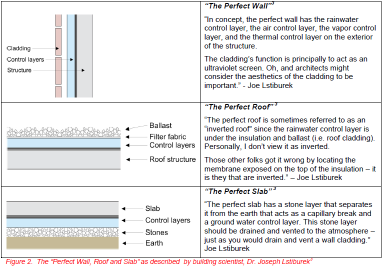
A successful, long-lasting building blocks heat, air and moisture flow on all six sides, inhibiting the damage functions of moisture, heat and ultraviolet energy. In principle, the ability to block HAMM and the damage functions seems straightforward (See figure 2). Unfortunately, a constant influx of new construction materials and the wide variety demanding climate variations encountered in actual construction make achieving the perfect wall far from easy in the real world.
Designers are forever baffled with the introduction of new material or specification changes and the appropriate design considerations for proper installations. Contractors must take these sometimes difficult-to interpret designs and put the pieces together in a manner to prevent unforeseen problems. Here lies the importance of proper oversight and investigation. Including a properly trained professional in building science and infrared thermography can be used as a discovery tool documenting all the factors of HAMM.
INFRARED THERMOGRAPHY AND HAMM
Infrared thermography is the only method that provides real-time heat monitoring with visual documentation of findings. As such, thermography is the ideal tool for studying buildings and the heat, air and moisture flows or patterns associated with HAMM. For more information on the use of infrared thermography in buildings, see Appendix G of the 2009, Energy Process Assessment Protocol4.
Let’s look more closely at how infrared thermography allows the user to observe HAMM.
Heat Flow and Infrared Thermography
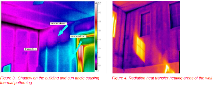
Heat is transferred from the sun to earth as radiation, heating our planet and buildings. This radiant heating shown in Figure 3 may cause patterning that is difficult to interpret due to shadowing and differential heating. Figure 4 shows thermal patterning due to radiation heat transfer from the sun, creating patterns not caused by inadequate insulation or other heat sources within the wall, ceiling, or floor.
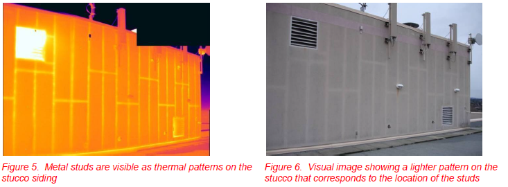
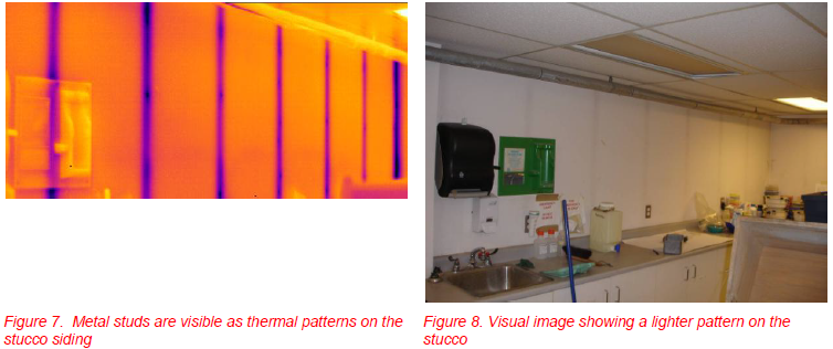
As heat flows through the building’s enclosure, it flows at differing rates depending on the conductivity of the materials within the structure. Metal is a great conductor for heat and metal studs become very apparent if a temperature difference between the inside and outside of the building surface is present. Figure 5 is an exterior view of the wall of a structure which is warmer inside than out. The metal studs are clearly visible due to their high conductivity while the lower conductivity of the fiberglass insulation results in cooler areas between the studs that show up darker in the thermal image. The visual image in Figure 6 shows a distinct patterning similar to the infrared image. This visual pattern is due to the warming from thermal bridging of the studs. In a cool climate, the warmer areas dry, minimizing water exposure, and collecting less dirt than the cooler, wetter areas between the studs.
When the same inspection is performed from the inside wall, the pattern is reversed, showing cooler studs. The stud bay in Figure 7 is a poor conductor, trapping the heat inside of the building. Unlike the lighter looking stud pattern in the visual image of Figure 6, the pattern of the interior wall at the studs is darker (Figure 8). The darker patterning on the interior’s visual image is due to cooler studs causing more condensation then at the stud bay.
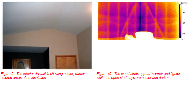
A thermal scan of a building using infrared thermography can locate poorly installed insulation as shown in Figure 9. However, at times, it may be difficult to interpret thermal images; as shown in Figure 10 of an uninsulated wall viewed from the interior on a very cold day. On days without a temperature difference between the interior and exterior surfaces, little to no thermal patterning due to conductive differences can be observed.
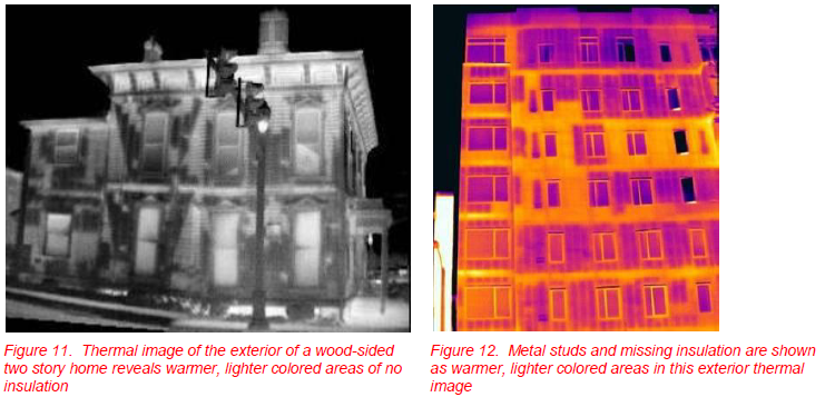
In many cases, a thermal scan of the exterior of a building can also determine the condition of the insulation (Figures 11 and 12). In both buildings the surface temperature inside is warmer, showing lighter-colored areas as having little or no insulation. Note that environment, exterior building materials and many other factors make exterior building thermography a difficult endeavor.
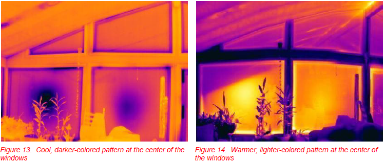
In addition to missing insulation, double pane windows can be observed with infrared thermography to determine failures. In Figures 13 and 14, the central thermal patterning suggests the glazing has come closer together at the center. The window image in Figure 13 was taken on a cold day and Figure 14 on a warm day, both interior views. Notice that the thermal patterning is within the center of the glazing. This patterning is due to the escape of the argon gas and failure to replace the gas. The pressure drops within the double panes causing the glazing to become concave. Since the centers of the two panes of glass are closer, greater heat transfer via conduction occurs creating the pattern visible with infrared thermography.
Air Flow and Infrared Thermography
Air flow through the building enclosure increases heat transfer via convection and provides a means of moisture transport. Without an effective, continuous air-barrier system, conditioned air escapes through the building envelope and exterior air flows into the building due to pressure differentials. It is clear that air movement is a very important factor in reducing energy consumption and solving condensation issues.
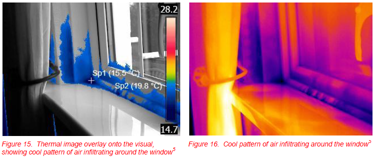
Windows or ―holes‖ in the building enclosure allow the occupants to see out and light in. Unfortunately, many are not properly installed. The window in Figures 15 and 16 show air infiltrating due to failed window seals.
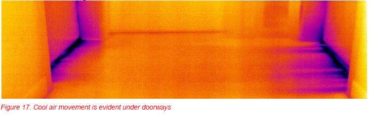
In many cases, pressure differences within the building are produced by fans, stack effect, or HVAC systems. Figure 17 shows cooler air flowing from the doors of two restrooms. In this case, the exhaust fans were on an energy-saving timer, shutting off when the rooms were unoccupied, increasing the room’s pressure from a now unbalanced HVAC system. This energy savings solution may be causing issues rather than helping due to condensation occurring within the restrooms.
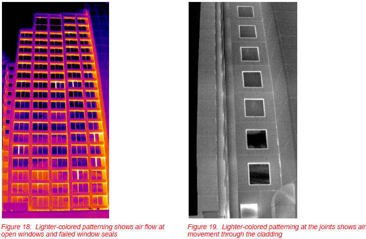
Pressure differences due to natural convection, HVAC system imbalances, or wind can cause pressure differences resulting in air movement through the building enclosure. Both Figures 18 and 19 show heated air flow through the enclosure to the cooler exterior. The exterior cladding in Figure 18 is concrete and the windows are sliding doors. Where the doors are partially open or have failed seals, heat can be seen escaping. The thermal image in Figure 19 shows an EIFS cladding with failed expansion joints especially visible at the corner joint. Due to the high pressure and temperature within the building, escaping heated air is observed as it comes in contact with the cladding.
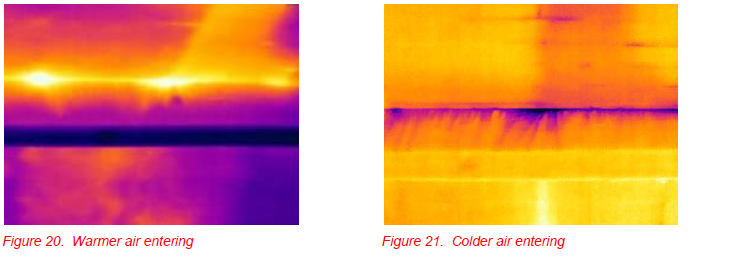
When performing building pressure tests to determine air leakage rates, infrared thermography is an excellent tool in locating leakage points and paths of travel through the enclosure. As the pressure differential is increased, any air leaking through the enclosure will transfer heat via convection to the surfaces it comes in contact with. Depending on the temperature of the air, patterns will appear cooler or warmer than the building’s surface. Thermal images showing the same ceiling area show warm (summer) or cold (winter) air entering the enclosure—heating or cooling the surface (Figures 20 and 21).
Moisture Flow and Infrared Thermography
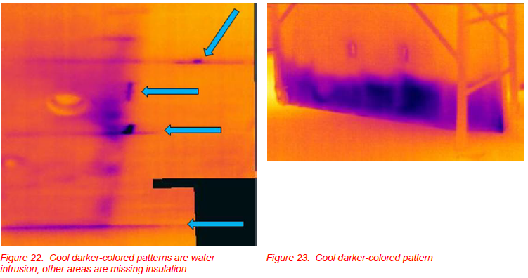
Moisture causes a majority of the damage in buildings and is typically the easiest to observe using infrared thermography. Due to evaporative cooling, water on a surface will produce a cooler pattern (see Figures 22 and 23). However, on a cooler day, inadequate insulation can also show a cooler pattern that may be confused with water intrusion. This is apparent in Figure 22 and creates an image difficult for the thermographer to interpret correctly.
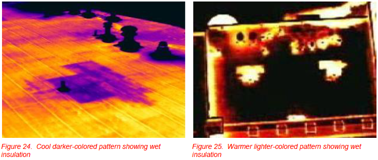
Due to water’s high thermal capacity, trapped moisture can provide a temperature difference observable with infrared thermography. In the morning, as the sun heats the roof, the building material heats quicker than the trapped moisture creating a cool pattern (see Figure 24). In the evening, when the sun sets, the roof material cools faster than the trapped moisture, creating a warmer pattern (see Figure 25).
SUMMARY
Understanding the controlling factors of the physical, chemical, and biological reaction within the building environment is important in understanding the building’s performance. Heat flow, air flow, bulk moisture, and moisture vapor flow or HAMM are the four major controlling factors and are the primary barriers required for a properly functioning building.
Infrared thermography is an excellent tool to non-invasively view and evaluate heat flow, air flow, and moisture flow within the building environment. In-depth knowledge of the use, operation, and limitations of the specific thermal camera is critical when used for building science applications. Even more important is an understanding of the building’s design and construction, with training in thermography and pertinent field experience to help interpret the infrared images.
REFERENCES
- Lstiburek, Joseph, ―Insight Energy Flow Across Enclosures‖ Insight, 028, December 2009. 2. McIlvaine, J., 2006 Building America. Industrialized Housing Partnership. (BAIHP). Final Project Report. September 1, 1999 - June 30, 2006. FSEC-CR-1663-06.
- Lstiburek, Joseph, ―Insight the Perfect Wall, Insight, 001, July 2010.
- Wood, S., IEA ECBCS Annex 46, Energy Process Assessment Protocol, Appendix G, Use of Thermography in Building Energy Assessment, 2009.
- Darragh O'Grady, images for figures 17-18, Energy Action, Ireland 2011
- Colantonio, Antonio and Theauvette, Michel; ―Specifying Infrared Thermographic Services for Large Buildings‖; InfraMation Proceedings, Volume 8, 2007.
- Colantonio, Antonio and Desroches, Garry; ―Thermal Patterns Due to Moisture Accumulation within Exterior Walls‖; Proc. InfraMation Proceedings, Volume 6, 2005.
- Colantonio, A. and Wood, S. ―Detection of Moisture within Building Envelopes by Interior and Exterior Infrared Thermographic Inspections‖ – InfraMation Proceedings, Volume 9, 2008.
- Wood, S., and Durston, L. ―Commercial Air Barrier Testing and the use of IR Thermography in Locating Air Leaks‖ - InfraMation Proceedings, Volume 10, 2009.
- Proskiw, G. and Phillips, B; ―Air Leakage Characteristics, Test Methods and Specifications for Large Buildings‖; Canada Mortgage and Housing Corporation; 2001.
ABOUT THE AUTHOR
Scott Wood, President of SWA, is a Level III thermographer and expert building science thermographer. Scott utilizes thermography for building science and condition monitoring. He has performed investigations on hundreds of buildings, revealing defects and providing corrective recommendations to prevent heat loss, air infiltration and moisture intrusion. Scott has taught Building Science Thermography classes since 2003, providing instruction in the use of thermography for building applications. As a private contractor, he teaches classes for the ITC and is the Technical Director for United Infrared’s MoistureFindIR™ module. Mr. Wood is frequently published and provides numerous clinics/workshops. He is the current Director of Building Sciences and Treasurer for the International Association of Certified Thermographers (IACT). Scott’s unique knowledge and experience in building science thermography allow SWA to assess buildings nondestructively, quickly, effectively, and comprehensively.
Related Articles
-
 Thermography Fundamentals
Know Your Subject Matter
Read the Story -
 Electrical/Mechanical
Five Years of Infrared Results at CNA – March 2005 through June 2010
Read the Story -
 Electrical/Mechanical
Identifying Gear Alignment and Lubrication Concerns
Read the Story