The Effect of Optical Obstructions on Temperature Measurement
InfraMation 2016 Application Paper Submission
Maud Hovens and Andy Whitcher
IRIS Thermovision and Tecpinions
ABSTRACT
There is anecdotal evidence that objects within the minimum focal distance of a thermal imaging camera will have an effect on temperature measurement. This paper shows that these effects are real and have a significant impact on temperature measurement. Many thermographers are unaware that items close to the lens of their camera will influence the results they obtain. The effect is not restricted to one field of thermography but applies to all applications as it is an optical phenomenon. The paper demonstrates real examples from several applications and quantifies the impact on temperature measurement. We hope that this paper will raise thermographer’s awareness of this phenomenon and help them to learn how to mitigate its effects; thereby improving the accuracy and reliability of their temperature measurements.
INTRODUCTION
In many instances we find that there are obstructions between the camera and the object we wish to measure the temperature of. Some simple examples are electrical equipment placed behind mesh for personnel protection or a building behind a fence. The normal reaction of a camera operator when faced with this problem is to place the camera up against the obstructing object and this seems to be for two reasons:
Firstly when the camera is placed so that the obstruction is within the minimum focal distance of the lens it cannot be seen in the image so the image looks better. The implication is “If I cannot see it, it is not there”.
The second reason has a little more thermographic ‘theory’ behind it. There seems to be a belief that if a hole in the obstruction is larger than the camera’s measurement spot size then putting the camera against the obstruction and ‘measuring’ through a hole will give a correct result.
Knowledge and experience have proved to us that obstructions can significantly affect our measurements. In Maud’s InfraMation 2015 Paper “How To Be Successful in Building Thermography: The Do’s and Don’ts in a crime scene case study” she showed that a thermographer of little knowledge had placed their finger in front of the camera lens whilst taking an image of a building and that this affected the temperature measured on the surface of the building across the entire image.
We have anecdotal evidence from our experience as furnace thermographers, where we noticed that the distance from the camera to the furnace peephole seemed to affect the measured temperature inside the furnace. In measurements in the electrical and industrial inspection field we know that it is not possible to take accurate measurements through a mesh window.
All of this experience led us to think further about the effects of objects within the minimum focal distance of the camera. This is an optical phenomenon and should be evident in all applications of thermography.
ELECTRICAL THERMOGRAPHY
Access to electrical equipment is sensibly restricted for safety reasons. This can take the form of mesh screens, fenced compounds or locked cupboards. In our first example we will look at a transformer inside a fenced compound.
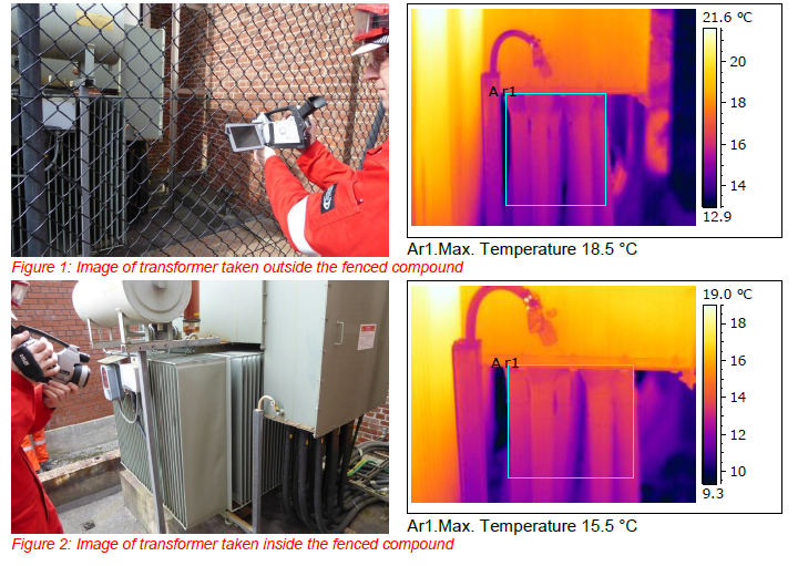
The temperature measured through the fence is higher than from inside the fence. This is because the apparent temperature of the fence is warmer than the temperature of the target. Extra energy is entering the camera from the fence which it assumes to be coming from the object itself so it reports a temperature that is too high. The difference in temperature is 3.0ºC (5.4ºF) which is 19% of the reading.
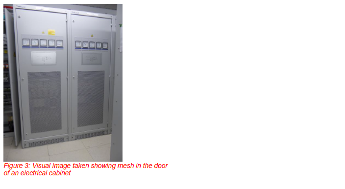
Below are two IR measurements. The first IR image is taken with the cupboard door opened. The second IR image is taken through the mesh in the cupboard door. Both measurements are made on the same spot.
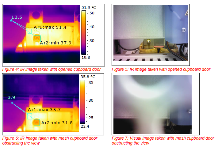
With the cupboard door mesh obstructing the view, not only are the absolute temperatures much lower, (Ar1: 15.7ºC (60.26ºF) lower) but also the temperature differences within the IR image are lower (3.9ºC (39.02ºF) instead of 13.5ºC (56.3ºF)).
INDUSTRIAL THERMOGRAPHY
Target: steam pipe
Again we have two IR measurements, one with mesh in between and one without. Both are on the same spot.
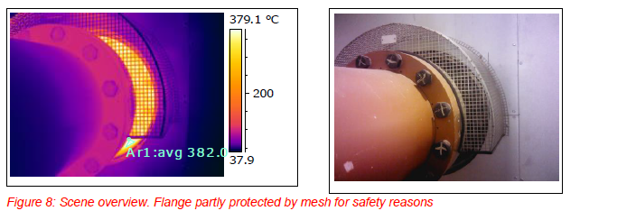
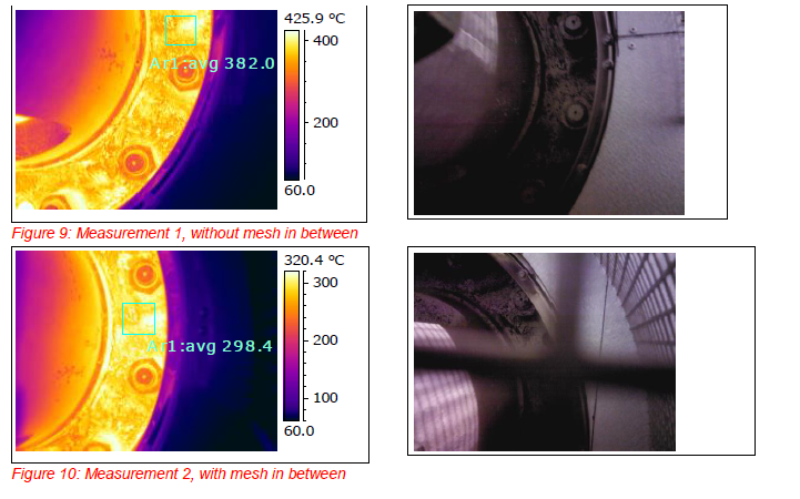
By putting the camera against the mesh, the mesh becomes within the minimal focus distance of the IR lens. The mesh is not visual in the IR image. But the presence of the mesh has enormous influence on the temperature measurement. A temperature difference of 83.6 ºC (182.5 ºF)!!!
BUILDING THERMOGRAPHY
Watch your finger!!!
In the image below the IR image is partly blocked by a finger within the focal length of the camera lens (up to 30 cm from the lens). The major implication for the temperature calculation of the infrared camera is illustrated in the example below.
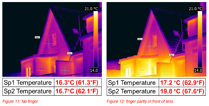
The finger in front of the lens leads to over 3 °C higher temperature measurement! And also the difference in temperature is 2.2 °C higher!
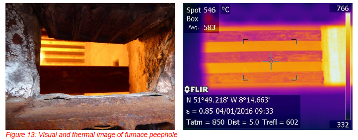
FURNACE THERMOGRAPHY
In furnace thermography the obstructing object is the casing of the furnace because we must always take measurements inside the furnace through a relatively small peephole. The target object is very hot, often around 800-1000ºC (1472-1832ºF) and the outside wall of the furnace is usually below 100ºC (212ºF). Restrictions of access near to the furnace peephole because of process piping, structural steel or the protective heat shield on a GF309 camera mean that the window may be only the central part of the image. A typical peephole and image are shown below.
To demonstrate the effect of the size of the peephole on temperature measurement we conducted an experiment. We found a furnace that has a peephole with a moveable door that we could close in increments whilst remaining focussed on one tube with the camera remaining in the same position. We then measured the apparent temperature of the tube at different door ‘sizes’ and plotted a graph.
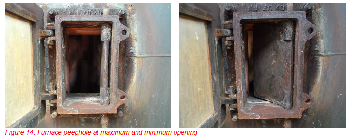
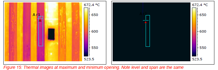
The peephole was closed in 10mm (approx. 0.5in) increments and the temperature on one tube measured. The values given here are apparent temperature (ε=1 and distance=0) to avoid confusion due to the object parameters of the complex thermal environment inside the furnace. Plotting the apparent temperature against the peephole opening we obtain the graph below:
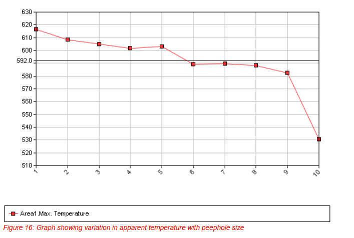
The graph clearly shows that as the door closes the apparent temperature of the tube appears to drop. The maximum temperature is 617ºC (1143ºF) and the accuracy of the camera is specified as ±2%. Taking the worst case measurement, the accuracy could be 4% of 617 or 25ºC. This gives us a threshold value of 592 ºC, the temperature below which the measurement is out of the camera accuracy range in the worst possible case. As can be seen above, this means that image number 6 onwards (when the peephole has been closed by 50mm (2”) are out of the camera accuracy range. The measurement with the door almost closed is 531 ºC (988 ºF), this is 86ºC (155ºF) lower then with the door fully open; a significant difference.
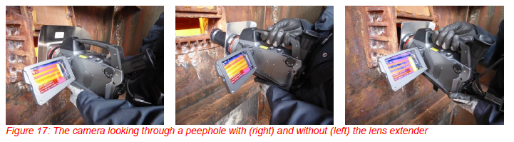
In practice, this shows us that to get accurate results we need the camera lens to be as close as possible to the peephole. The standard configuration of the FLIR GF309 means with the camera heat shield that this is difficult particularly if you want to look at any angle other than straight ahead. A lens extender, which is available as an accessory, allows us to put the camera lens right in the peephole which avoids any of the problems shown above.
The image below shows the camera looking into peephole with and without the lens extender. The centre image is with the camera withdrawn to show the extender configuration.
The thermal images obtained with and without the lens extender are different and have different measurement results.
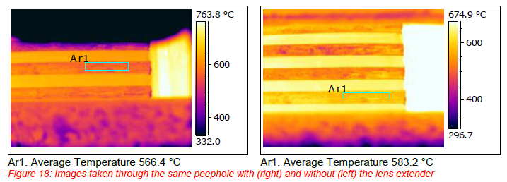
The temperature taken without the lens extender is 16.7ºC (30ºF) lower than the temperature taken with the extender. In percentage terms the difference is 2.9%. This is because the end of the lens extender is inside the peephole thus eliminating any effect of the optical obstruction within the minimum focal distance of the camera. Better accuracy in measurement is the result. Another benefit is that by using a lens extender more tubes are in sight. Larger amounts of tubes can be inspected.
BACKGROUND EXPLANATION
The demonstration below, originally an idea by Bernd Schonbach, shows how an obstruction within the minimal focus distance of the camera works as an aperture stop.
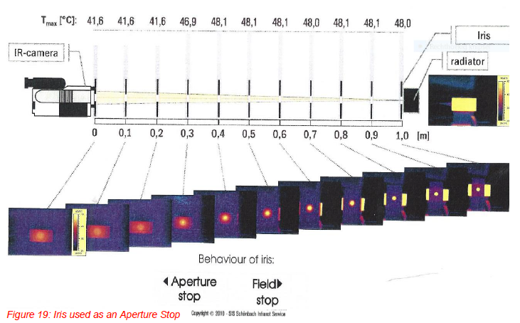
In the experiment above the iris is moved from 1m away from the camera towards it in 100mm (4”) increments. Initially the iris behaves as a field stop. That is to say that part of the radiator is visible through the iris and the temperature measured through the iris remains constant as the iris moves towards the camera.
When the iris reaches approximately 0.3-0.4m (12-16”) away from the camera its behaviour changes from a field stop to an aperture stop. Now the whole of the radiator is visible through the iris and the iris is limiting the amount of radiation entering the camera towards the detector. The effects of an aperture stop are:
- Limits the amount of radiation towards the detector
- Changes the thermal resolution (contrast)
- Increases the depth of focus
Note that the Field Of View (FOV) remains the same.
Aperture stops exist in the camera already in the form of the lens mount and other components and their effect on the amount of radiation entering the camera must be taken into account during its optical design. Lenses have the highest precision in the center part of the optics. At the edges lenses are not as perfect and there are more effects of geometric aberrations like: spherical; astigmatism; coma (curvature of the field image) and distortion of the image (barrel distortion and pincushion distortion). Also the chromatic aberrations, dispersion change of refraction index with wavelength are more prominent at the edges. For this reason, it might be an advantage to have an internal aperture stop for more precise temperature measurements giving:
- Better focus over the detector surface
- Larger focal depth
- The ability to measure higher temperatures
MEASUREMENTS THROUGH A PINHOLE, THE PERFECT OBSTRUCTION?
What happens if we look with an IR camera through a perfect pinhole? The perfect pinhole is the pinhole size where you will have the longest focal depth.
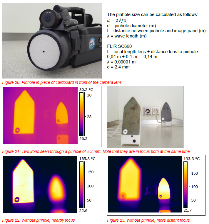
The positive side-effect of measuring through a pinhole is a larger depth of focus. You can have far and near objects in focus at the same time. The measured temperatures, temperature differences and the image contrast is however very much lower. The benefit of a larger depth of focus by measuring through a perfect pinhole does not outweigh the effect of limiting the amount of radiation towards the detector and the lower image contrast.
SUMMARY
1. An object within the minimal focus distance of a camera will not be seen by an IR camera. But no reliable absolute temperature measurements or temperature differences (delta T) can be measured. The contrast is also much lower.
2. An object placed between the camera and the target but within the minimum focal distance of the camera will affect the measurement of the temperature of the target. How large the effect is and whether it is positive or negative depends on the environment and the properties of the obstruction.
3. To obtain the best results objects within the minimum focal distance of the camera should be avoided wherever possible and it is not possible to make accurate temperature measurements through mesh windows.
4. In the furnace environment the lens extender is a useful accessory, not only for more correct temperature readings, but also for larger field of views.
5. The positive side-effect of measuring through a pinhole is a larger depth of focus. This does not outweigh the effect of limiting the amount of radiation towards the detector and the lower image contrast.
ABOUT THE AUTHORS
Andy Whitcher is a keen sailor competing at national level within the UK. When he is not sailing, he is the director of Tecpinions ltd, a UK based thermographic consultancy. He holds an honours degree in Chemical Engineering and is a Chartered Chemical Engineer Andy has 24 years’ experience in the oil industry as a Process Engineer, Inspection Engineer and Thermographer. He is an ITC Level 3 Thermographer and holds a BINDT Level 3 in Thermography including all three specialist application qualifications. Andy is also a Licensed Instructor with ITC teaching Level 1, Level 2 and Gas Detection Courses. Please contact Andy at andy@tecpinions.com or visit at www.tecpinions.com
Maud Hovens owns IRIS Thermovision, a company that specializes in thermography. She conducts inspections and investigations, acts as a consultant and provides training at home and abroad, for individuals, businesses and governments. Her company is a licensed partner of the ITC (Infrared Training Centre), the world’s largest educational institution for thermography and contributes in new training material for ITC.
Maud Hovens is a professional and is level 3 certified Infrared Thermography, ITC, BINDT, ASNT NDT and ISO 9712. She is active in the thermography field almost 20 years and the first level 3 certified in the Netherlands. She takes her role as a knowledge carrier very seriously. Recent publications: Measurement and Thermography, SDU publishers Thermal Imaging, Fire Academy (Dutch Institute of Physical Security). Please contact Maud at maud@iris-thermovision.nl or visit at www.iris-thermovision.com