Interesting IR Opportunities Found Over 14 years as a Distribution Line and Substation Thermographer
InfraMation 2012 Application Paper Submission
Ken Leonard
Progress Energy Carolinas
ABSTRACT
Performing IR surveys primarily on distribution lines and substation equipment, but also on electrical vault equipment and transmission lines over the last 14 years has presented some interesting IR opportunities, aka thermal anomalies. Some were puzzling, some illustrative of problem severity, and some just downright unsafe. This paper presents the most interesting, including equipment falling apart on repair, at least one bullet hole, and one smoldering support rope.
INTRODUCTION
Fascinating is a good word to describe my IR survey experience at the electric power utility Progress Energy Carolinas. It has never been boring and sometimes is too exciting. It is also important work and the pressure is always on to ensure we do our IR surveys correctly.
We want customers to take us for granted. That’s a real compliment. They expect the lights to come on when they flip the switch. Reliability is a very important part of our Condition Monitoring program and IR thermography is an important aspect of ensuring reliability. But it’s not the only part. Progress Energy has a great CM team.
We have a great repair crew that responds when needed. I’m one of the lucky ones who get to find the problems. Though there are numerous IR anomaly finds, or “opportunities,” that are similar to each other, some are truly unique and can stretch the limits of what one would expect. These keep the thermographer’s life interesting. This paper shares some of my most interesting opportunities.
SAFETY
Progress Energy Carolinas has a strong focus on both customer safety and employee safety. We really stress safety in the workplace. And safety is a priority that stands with reliability in working with our customers. Recently strong winds took down power lines and some customer service lines, affecting over 12,000 of our customers. I noticed the service line from the pole transformer to a home was knocked loose and damaged, although the lights were still on. But the wiring was precarious; any further disturbance could cause a fire. It was not a safe condition and we had to cut service to protect the customer. When a lineman asks me if a situation such as this is safe, my reply is, “It is safe if you would let your family sleep in this home tonight.”
For example, we never enter a substation without a job briefing. Don’t touch the gate until a safety survey is completed. We look for wires on the fence, oil leaks, bad smells, bad noises, smoke, or anything out of the ordinary before entering.
Distance is your friend when it comes to arc flash and electric shock. Distribution and transmission line surveys are typically done from safe distances, especially when you have a high resolution IR camera with a telescope. I use my telescope all the time. Even when I could get closer, I will often stay back and rely on my IR optics.
Enclosed areas like vaults, battery rooms, and even substations have specific safety procedures to protect both workers and the public, as close working distances are often unavoidable. Where possible, the IR camera is also a valuable safety tool allowing previewing an enclosed job site from a distance before entering.
OVERLOADED CIRCUIT FEEDING METAL FAB
Figure 1 is an IR and visual image pair showing an overloaded feed to a metal fabrication facility. The IR image was taken with a FLIR P640 camera with a 12 degree lens from about 150 feet. The conductor to the building is a quadraplex feed with three 500 MCM (about 0.81 inch diameter each) hot wires and one 4/0 neutral (about 0.45 inch diameter). The temperature rise is omitted as any significant temperature rise in this case indicates a critical problem. Wires, pole mounted transformers, and transformer connections all are overloaded.
What happened? The company rewired their facility to add more machinery, increasing production capability. But they didn’t notify the utility. The new load requirements after the rewiring were considerably greater than the original design. We corrected this as soon as possible by increasing the conductor size and running a parallel service.
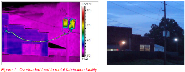
This event illustrates one of the key elements of a good condition monitoring program: COMMUNICATION. Though our customers are not part of our CM team, the thermographer is. I was fortunate to shoot this with my P640 before a serious failure occurred.
POLE MOUNTED TRANSFORMER CONNECTION FEEDING FIRE STATION
Figure 2 shows an extremely bad transformer connection that feeds a fire station. This is the hottest pole mounted transformer connection I’ve encountered at over 240 F° temperature rise. It is so hot, one can see a decent reflection off the painted transformer case. With an emissivity of 0.95 that’s a 5% reflection! With calm air, 50 feet range, 1.5” hot spot, and the FLIR P640 plus12 degree lens, this measurement is reasonably accurate. Though every customer is important, fire stations, hospitals, police stations, and other emergency type facilities that serve the community are critical to the safety of all.
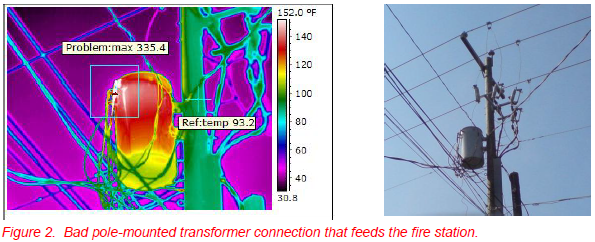
The thermal tuning in Figure 2 was adjusted to enhance the reflection off the transformer. The reference temperature was taken on the pole as everything on the transformer was overheating due to the bad connection. Normally, we take like-to-like, usually comparing same location on two different phases under same load and environmental conditions.
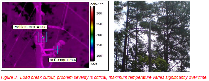
LOAD BREAK CUTOUT
This pole-mounted load break cutout is interesting for a couple of reasons. One, it was extremely hot with over a 300 F° temperature rise. Perhaps more interesting was the temperature variation over time. This was a calm day with no wind. But over a 15 minute time period, the maximum temperature reading went from 335 to 380 to 202 to 430, then to 413.8°F. It makes one wonder what this was feeding–perhaps a pumping station or other load that varies significantly over short periods of time? In any case, it is a critical problem.
FAILING JUMPER
This 477 ACSR (Aluminum Conductor, Steel Reinforced) jumper is failing in the middle! These are stranded conductors with steel strands in the center for strength and aluminum strands wrapped around the steel for higher electrical conductivity. Perhaps this got kinked somewhere along the way and finally started failing with a couple of strands breaking. We don’t really know at this point. Though the entire jumper is hot, the Area Max feature in the FLIR Reporter software (Figure 4) clearly shows the hottest spot is not at a connection, but somewhere in the middle of the jumper.
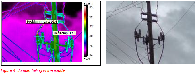
The jumper is feeding a pothead for underground conductor to a 23 kV to 4160 V distribution substation about 500 feet away that services a large cosmetic manufacturing company. Taken with my FLIR P640 and 12 degree lens at a range of about 70 feet, the 1”-diameter tarnished aluminum conductor is probably close enough for a good measurement. The emissivity is unknown, but set to 0.9 with a Treflect of 70°F (Figure 4). This means maximum temperature of the jumper is actually higher than shown. Setting the emissivity to 0.5 changes the maximum reading to 147°F for example. In any case, this is another example of the nature of the problem overriding the temperature rise severity criteria. A jumper shouldn’t be failing in the middle. The problem is critical and needs repair ASAP.
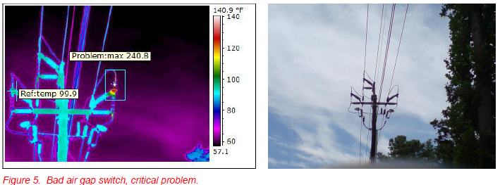
BAD AIR GAP SWITCH 23KV LINE
These air gap switches have a history of being problematic due to numerous moving parts and difficulty of installation. Progress Energy is beginning to phase these switches out and is replacing them with a simpler model that is easier to install properly. This switch is in-line at an underground service feed allowing the distribution operations personnel the flexibility of managing this portion of the distribution service.
This is a critical problem. If replacement parts aren’t immediately available, repair personnel can “jumper” around this problem, temporarily removing the switch from service, but ensuring uninterrupted service. When replacement switch arrives, it replaces the failing switch and the jumper. Temporary fixes such as this can sustain reliability while waiting for replacement parts.
TRANSFORMER COOLING PROBLEM
Not all problems found during IR surveys of electrical equipment are electrical in nature. Figure 6 shows a transformer cooling problem with 3 of the 8 front cooling fins not circulating oil. They are cooler than the other fins and can be seen in the IR image as the darker, vertical lines on the left side of the transformer. Normal operation for this type of gravitational, natural convective cooling is for the top of the fins to be warm, cooling as the oil nears the bottom. This type of problem usually indicates a transformer off level, sometimes combined with low oil level. In this case, leveling the transformer, which was only 7/8” off level, solved the problem. Low-oil-only would be indicated by all the cooling fins not circulating properly.
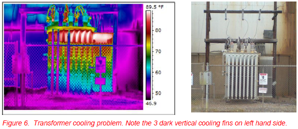
Many transformers have pumps that circulate the oil. The thermal patterns are the same. Non-circulating fins in the pump case have the additional possibility of pump failure, backward running pump, and broken impeller giving partial circulation in addition to off level and low oil. Some transformer designs have groups of circulating cooling fins at different heights. Warmer environmental temperatures cause the oil to expand. The design is such that as it gets hotter, the expanding oil level reaches the higher cooling fin tops and starts circulating through those as well. This increases cooling in hotter weather. The transformer in Figure 6, however, has only one level.
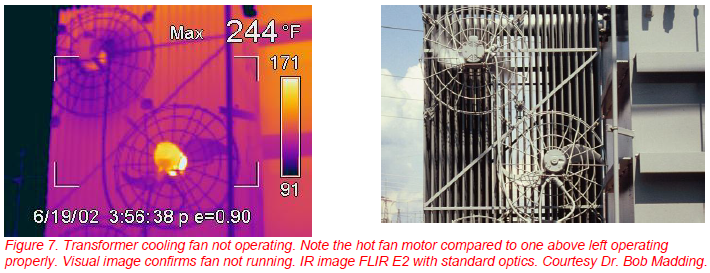
While we’re on the subject of transformers, many transformers have fans that circulate air across the fins to enhance cooling. The fans are driven by air temperature. When it gets hot enough, they automatically turn on. When performing substation IR surveys, it is important to operate these fans even though they may not be on due to lower temperatures. One needs to verify proper operation. Figure 7 gives an example of a bad fan. The problem is obvious by visual observation. The IR image confirms something bad is happening with the fan motor. It is very hot and not turning.
UNDERGROUND DIP ARRESTERS
‘Underground dip arrester’ is an interesting phrase to the uninitiated. These are lightning arresters on a dip pole or a riser pole. A dip pole is a pole that has electrical components on it to feed the overhead power to underground lines. A riser pole is the opposite, taking power from underground and feeding it to overhead lines. In this case, we’re dealing with a riser pole, but we still call them dip arresters.
Like other lightning arresters, these represent indirect measurements. The heat is being generated inside the ceramic or polymer insulating housing due to leakage current. There should be no leakage current in normal operation. Sometimes, these polymer type arresters are improperly installed by over-tightening a nut on top which results in a crack or cracks in the polymer housing. A cracked housing allows moisture in which compromises the integrity of the MOVs (Metal Oxide Varistors) that are the operational heart of most lightning arresters. They begin to leak current, and eventually fail, often catastrophically.
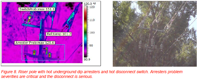
A warm arrester is a “shoot and scoot” situation, meaning personnel should leave the area asap. With the FLIR P640 and 12 degree telescopic lens, I was able to get the IR image in Figure 8 from a range of 100 feet, providing a significant margin of safety over what it would be if I had to use a lower resolution IR camera without a telescope. For components in open air such as these, the energy from an arc flash, aka arc blast, drops roughly as the square of the distance. At 100 feet, one would get 1/16 the energy than at 25 feet.
Figure 8 shows a riser pole with 3 hot underground dip arresters and a hot disconnect above them. Four problems on one pole! The dip arresters are all critical problems and the disconnect switch is a serious problem.
The hottest arrester I have been able to document is shown in Figure 9. The temperature rise is about 74 F°. This is an indirect reading, so the actual internal temperature rise would be several times greater. Though we don’t know exactly how much greater, three to four times is probably not unreasonable. So, the internal temperature rise on this arrester could easily be 200 to 300F°. It bears repeating: Any temperature rise due to internal heating on a lightning arrester is deemed a critical problem.
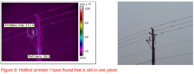
Richard Strmiska of Sumter Electric Cooperative wrote an interesting paper on distribution lightning arresters1 presented at InfraMation 2003. Having surveyed dozens of distribution lightning arrester, the largest temperature rise he found was about 40F°
BULLET HOLE
This was first published in the InfraMation 2005 InfraMation Proceedings2, but bears repeating. Figure 10 shows a very unusual situation where a bullet pierced a voltage regulator tank allowing most of the insulating oil to drain out. Why this didn’t fail catastrophically is unknown. The center tank shows anomalous warm oil and only about a fourth of the way up. Closer inspection revealed a bullet hole. I used a 7 degree telescope lens on our FLIR P65 IR camera to document this from a distance.
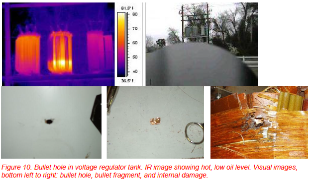
The bottom row of visual images in Figure 10 shows some of what was found on the autopsy of this regulator with the bullet hole on left, the bullet fragment in middle, and some of the internal damage done by the bullet. Whether an accident or intentional, this was certainly a very reckless action on the part of the shooter.
SMOLDERING ROPE
Figure 11 shows one of several very hot connections in a transformer bank. The center transformer is 250 kVA and the outer transformers are 167 kVA. This suspected overload situation occurs between about 5:00 PM and 9:00 PM.
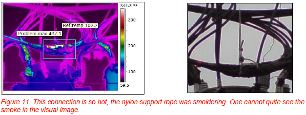
MSDS (Material Safety Data Sheets) don’t give a flashpoint for nylon. The melting point of nylon 6.6 is given as 492.8 F. The nylon rope support appears to be insulated somewhat from the hot spot which shows higher temperatures at the top, probably because the electrical insulation there is being melted away. This was found about two weeks before this paper was submitted so is still undergoing evaluation. Repair is scheduled for as soon as possible. This is a dicey situation.
SUMMARY
The above examples are just the tip of the utility thermographer’s iceberg when it comes to finding problems with IR. There’s no end to the challenges and excitement of finding thermal anomalies in vaults, distribution lines, substations, transmission lines, and other associated electrical components that bring electrical power from the generating station to the customers. We work in all sorts of environmental conditions from high temperatures and high humidity to cold, icy weather. We do get a break when it’s raining or snowing, but other than that, we’re out there for our customers. We are robust and so is our equipment.
ACKNOWLEDGEMENTS
The author gratefully acknowledges the contribution to writing and editing this paper by Dr. Bob Madding, President, RPM Energy Associates, LLC. I would also like to thank our Condition Monitoring team members at Progress Energy Carolinas for their unfailing support.
REFERENCES
Strmiska, Richard; Lightning arresters’ effect on power line reliability; Proc. InfraMation; 2003
Leonard, Ken; IR Situations in the Field—Analysis and Impact; Proc. InfraMation; 2005
BIOGRAPHICAL SKETCH
Ken has spent 31 years in the electrical field. He holds an unlimited NC electrical contractor license. He is a first class lineman, distribution equipment technician, and ITC level III thermographer. Ken has spent 14 years as a thermographer working primarily on distribution lines and substation equipment, as well as on electrical vault equipment and transmission lines. This paper is Ken’s sixth contribution to the InfraMation Conference as primary author or co-author.
Related Articles
-
 Thermography Fundamentals
Know Your Subject Matter
Read the Story -
 Building Science
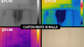
Three Ways the Pest Professional Can Use Infrared Thermography
Read the Story -
 Electrical/Mechanical
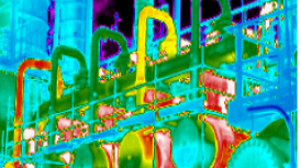
Positive IR Results In the Refining Industry
Read the Story