Normalizing the E-values of Components on a Printed Circuit Board
InfraMation 2009 Application Paper Submission
Rudie Bennett
Saab Avitronics (South Africa)
ABSTRACT
This paper describes the development and application of a method to normalize the emissivity (e-value) of various components on a populated PCB board. This technique proves particularly useful for boards and system parts when no other thermal images are available for reference. It involves spraying the board with a pre-tested coating that does not harm the PCB board.
After the coating dries, the board can be gradually powered up until the suspect or faulty component heats up. The coatings utilized during the development of this method are commercially available conformal coatings designed to protect and seal printed circuit boards against moisture and dust. These transparent coatings are widely approved for professional and military applications, making the technique relevant for PCB manufacturing.
INTRODUCTION
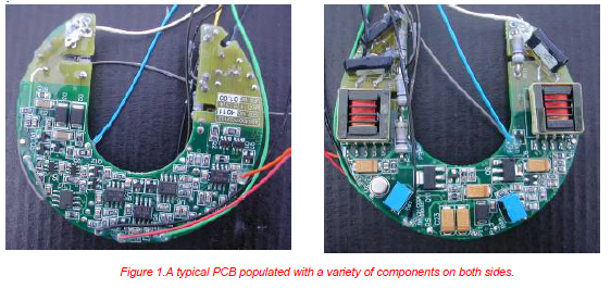
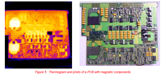
Printed circuit boards (PCBs) are populated with diverse components from various manufacturers, each applying unique finishes to their components. Figure 1 illustrates a typical PCB board populated on both sides. As technology advances, the density of components increases, introducing a wider variety of components into the field.
Understanding the thermal characteristics of a PCB allows for efficient thermal checks on every board produced during PCB manufacturing. Numerous thermal test setups and software solutions exist to evaluate the thermal image of each board. These setups become increasingly cost-effective with larger production runs. Boards that deviate from the preset thermal image are flagged for further investigation. In these setups, the e-value or relative temperature of each component under specific conditions must be standardized. This requires consistent finishes for components across different PCB boards, as calibration of the testing equipment is time-intensive. However, even when components perform to specification, e-values may vary between manufacturers or production batches.
When repairing units used in the field over extended periods, discrepancies in the IR profile between the original and repaired boards are nearly unavoidable. Such issues arise because post-production changes—whether from component replacement or finish changes—can invalidate the original thermal map. This problem is especially critical in determining what PCBs are used for in high-stakes applications, where thermal stability is essential.
Additionally, metal components often have low emissivity, while plastic components exhibit high emissivity. Over time, contaminants like dirt, dust, and oils further affect emissivity, making accurate thermal imaging difficult. These factors complicate the interpretation of IR scans, even for experienced thermographers. Employing a trained thermographer for production or repairs can become prohibitively expensive, particularly when results are uncertain.
To address these challenges, a simplified method was developed to streamline emissivity normalization and make IR scanning more practical and cost-effective. This approach is particularly relevant for PCB manufacturing, where ensuring uniform thermal performance is vital across both production and repair phases.
Related Articles
-
 sUAS/Drone
Aerial Solar Thermography and Condition Monitoring of Photovoltaic Systems
Read the Story -
 Electrical/Mechanical
Beware What You Cannot See: A Practical Application of the Use of IR Windows
Read the Story -
 Thermography Fundamentals
Geometry effects; hedging your bet on emissivity!
Read the Story